D1 · Publication Volume 17
Explicit Geological Modelling
sections, strings, wireframes and manual control
Learning objectives
By the end of this lesson, the learner should be able to explain explicit surface construction; organise plan, section and drillhole constraints; build strings and triangulated surfaces without confusing artistic control with evidence; test section-to-section correlation; and document manual edits so that a wireframe remains a reviewable geological interpretation.
Explicit modelling represents a geological boundary directly. The modeller places or edits lines, points and triangles that define the surface. This can give precise local control and make geological reasoning visible, but every unrecorded vertex movement can also become a hidden interpretation.
Sections as interpretive workspaces
Sections should be chosen to expose geometry, not merely laid out at a fixed spacing. Include sections along and across structural grain, through critical intersections, along drill fans and across areas where scenarios diverge. Record section plane orientation, thickness of projected evidence and which observations lie off the plane.
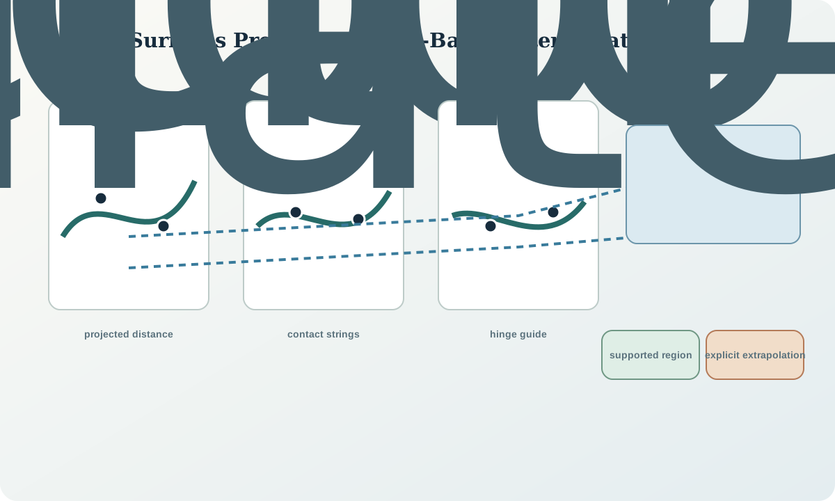
Projection can create apparent contradictions. A contact observed tens of metres away from a section may project across a fault or fold limb. Display projected distance and avoid snapping off-section data to the plane without recording the transformation. Linked plan, section and 3D views help identify when a neat section is inconsistent with surrounding evidence.
Strings, contours and correlation
A string is an interpreted trace of a surface or boundary. Give it object identity, section or plane identity, direction, closure state, source constraints and edit history. Avoid using one polyline for several geological meanings. A fault trace, stratigraphic contact and model clipping edge may coincide visually but have different topology and lineage.
Correlation between sections is a geological hypothesis. Before triangulation, identify which strings correspond, where they split or terminate and whether their vertex order is compatible. Crossing correlations can twist a surface. A one-to-one vertex connection is not required, but the resampling rule should preserve sharp bends and avoid artificial oscillation.
Triangulation and surface control
A triangulated surface approximates a boundary with vertices, edges and faces. Triangle size should respond to constraint density, curvature and downstream queries. Extremely long thin triangles can bridge unsupported areas and create unstable normals. Excessively dense regular triangles imply detail without evidence and increase opportunities for self-intersection.
Use control lines where geology justifies them: fold hinges, unconformity edges, intrusion margins or fault cut-offs. Distinguish hard constraints that a surface must pass through from soft guides that influence shape. Record smoothing, snapping, decimation and repair operations. If a manual edit moves geometry away from accepted constraints, it needs an explicit geological reason.
Terminations, boundaries and extrapolation
Every surface needs a boundary rule. It may terminate against a fault, truncate beneath an unconformity, pinch out, intersect topography or reach the model boundary. An arbitrary clipping polygon should not be presented as a geological termination. Store model bounds, data limits and interpreted geological extents as separate objects.
Extrapolation should be visible. Mark triangles or surface regions by distance to constraints, supporting section interval or interpretation class. Where the surface is deliberately continued to close a volume, label that continuation as construction geometry rather than observed continuity.
Quality controls and limitations
Check for duplicate vertices, zero-area faces, inconsistent normals, holes, self-intersections, extreme aspect ratios and unintended bridges. Compare the surface back to all accepted contacts in independent views. Inspect oblique sections that were not used to draw the strings. Calculate residuals, but also inspect direction: a small perpendicular distance can conceal a large along-hole or along-section mismatch.
Explicit modelling is not inherently more “manual” in quality or more “geological” than implicit modelling. Its advantage is local geometric control; its risk is undocumented subjective editing and difficulty propagating new data consistently. The correct comparison is between transparent rules and validation, not between labels.
Synthetic worked example
Four cross-sections in the fictional volume show a folded marker horizon. The first interpretation connects matching traces directly, producing a saddle-shaped twist between sections two and three. Review reveals that one trace was projected from the opposite fault block and another represents an erosional remnant rather than the continuous horizon.
The revised explicit model separates the blocks, adds a hinge guide supported by three orientations and terminates the remnant at the erosional surface. A closure extension at the lower model boundary is tagged as construction geometry. An unused diagonal section shows that the revised surface honours contacts within their tolerances without the earlier twist.
Practice and review checklist
Construct a simple surface from three sections and a plan trace. Preserve the initial strings, triangulation parameters and every edit. Then test:
- Are projected distances visible on each section?
- Can every string be assigned one geological meaning?
- Do correlations cross or reverse vertex order?
- Are terminations geological, data-limited or model-boundary clips?
- Where do triangle size and shape exceed local constraint support?
- Does an unused oblique section reveal an artefact?
- Can another reviewer reproduce the final surface from the saved constraints and edits?
Decision implications and integration
An explicit surface becomes authoritative only after its object identity, topology, validation and version are accepted. Store source strings and control lines with it. Do not export only the final mesh if reconstruction matters.
Before converting the surface into solids or domains, state which side represents which unit, how faults or unconformities truncate it and whether it is open by design. Those relationships are inputs to topology, not visual styling.
Sources
- LoopStructural 1.0, contrasts direct surface representation with implicit level-set construction.
- Three-dimensional geologic maps and visualization, describes assembling constrained surfaces with interaction rules.
- Techniques for improved geologic modeling, discusses mapper control, interpolation and uncertainty.
- Simple Feature Access, provides common concepts for geometry and validity relevant to surface components.