D1 · Publication Volume 17
Fault Frameworks
fault hierarchy, offset, termination and branching
Learning objectives
By the end of this lesson, the learner should be able to define faults as geological objects rather than decorative surfaces; construct a hierarchy and interaction graph; distinguish observed trace, interpreted surface, displacement and damage-zone concepts; represent termination, branching and crossing alternatives; and test how the fault framework changes unit connectivity and model purpose.
A fault framework partitions the model before or while other surfaces are constructed. Small geometric errors can change which units touch, which blocks communicate and where a target continues. Fault modelling therefore requires explicit kinematic and topological assumptions, not only a triangulated plane.
Fault object and evidence model
Separate the fault identity from its representations. Evidence may include mapped trace, drillhole intersection, oriented structure, offset marker, geophysical gradient, geomorphic expression or interpreted section trace. Each constrains a different aspect and scale. A fault intersection without orientation does not define a unique surface; a geophysical lineament does not by itself prove displacement.
Record surface geometry, polarity or facing where relevant, movement hypothesis, displacement evidence, active interval or event order, confidence and uncertainty. Keep the damage zone, alteration halo and modelling surface distinct. They may overlap spatially but answer different questions.
Hierarchy, chronology and interaction graph
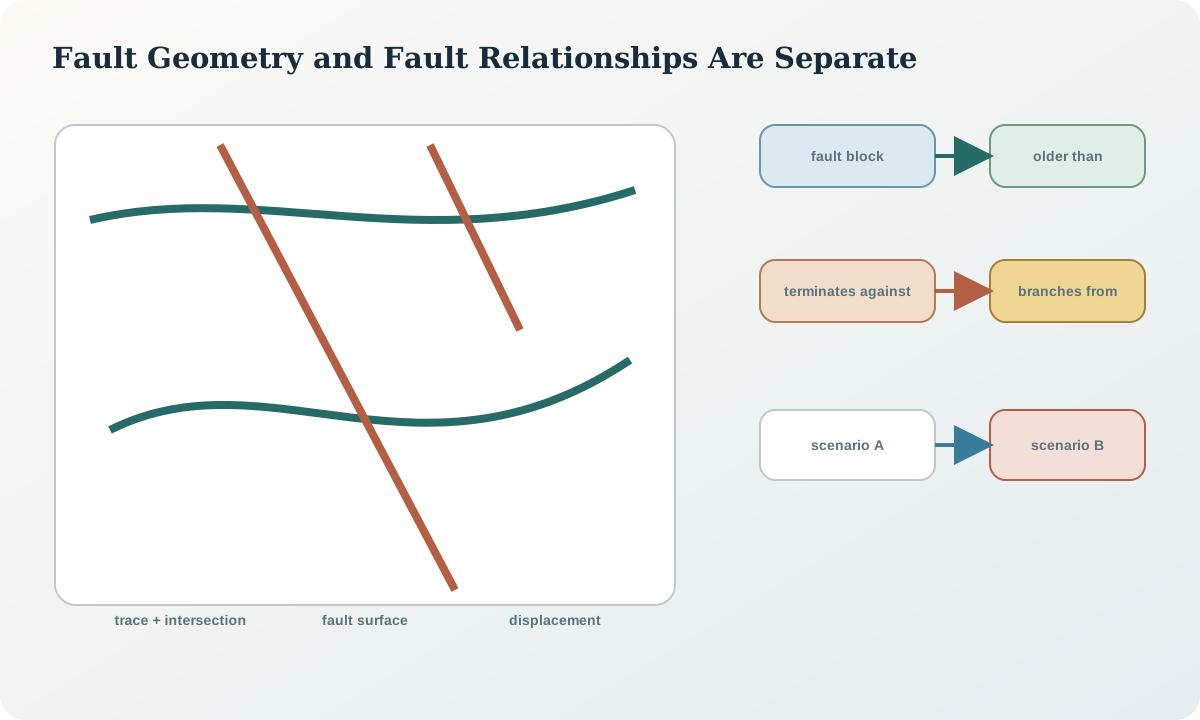
Build a graph whose nodes are faults and geological packages and whose edges express cuts, displaces, terminates against, branches from, merges with or is older than. The graph should be internally consistent. If fault A terminates against fault B while B is interpreted as older and displaced by A, the contradictory relations need resolution or separate scenarios.
Hierarchy can be based on event order, displacement scale or modelling role. State which. A first-order domain-bounding fault may require explicit displacement and separate interpolation blocks. A minor fault may be represented only where it affects the decision. Do not equate cartographic line length with structural importance.
Geometry, displacement and slip uncertainty
A fault surface defines location; displacement describes how features correspond across it. They are separate unknowns. Constrain geometry using traces, intersections and orientations. Constrain displacement using offset markers, stratigraphic cut-offs, repeated or omitted sequences and kinematic evidence. Record whether displacement is constant, varying, inferred or not represented.
Apparent offset in one section can differ strongly from true slip. A surface can honour intersections while using the wrong displacement direction. Test marker restoration or at least compare predicted cut-offs in multiple directions. If slip is unknown, preserve a range or structural scenarios rather than inventing a precise vector.
Termination, branching and crossing
Fault surfaces can terminate within the model, reach the model boundary, merge, branch, cross or be truncated by younger structures. Each case changes topology. An artificial taper used to close a mesh is not necessarily a geological tip. Distinguish an evidence-supported termination from a computational closure.
At crossings, define which fault is continuous and which is displaced, or retain alternatives. Branches should share a consistent junction geometry without sliver gaps or duplicate overlapping faces. Inspect the framework as a graph and in 3D sections; one view rarely exposes all invalid relations.
Fault blocks and downstream consequences
Use the accepted fault framework to partition the model volume into fault blocks. Give every block a persistent identity. Then test whether stratigraphic surfaces are continuous, offset or independently interpolated across each boundary. The choice affects extrapolation and uncertainty.
Connectivity is purpose-specific. A zero-thickness modelling surface may separate lithological domains, while a downstream flow model may need fault-zone transmissivity and thickness. The structural model should expose the boundary and uncertainty without claiming a property it does not estimate.
Synthetic worked example
Two steep structures cross the fictional volume. Sparse drillholes allow either a single through-going fault with a splay or two crossing faults of different ages. Both scenarios honour the observed intersections. Scenario A predicts the target horizon displaced northward and connected at depth; Scenario B predicts two isolated target lenses.
The framework records two graphs, separate surface and displacement parameter sets, and the observations shared by both. A proposed drillhole is tested against scenario divergence. It crosses the predicted target in both cases but encounters the second fault only in Scenario B, making that intersection a discriminating observation.
Practice and review checklist
For a two- or three-fault interpretation, create a relation table and graph. For every edge, cite evidence or mark it as assumption. Then review:
- Are fault location and displacement represented separately?
- Which structures partition interpolation domains?
- Where are tips, branches and crossings supported?
- Does event order agree with truncation and displacement?
- Do all blocks have stable identities and non-zero valid volumes?
- Which downstream connectivity result changes between plausible graphs?
- What new observation would best distinguish them?
Decision implications and integration
An adopted framework should include fault objects, source constraints, relationship graph, geometry version, displacement hypothesis, block partition and scenario status. Downstream surfaces must reference the exact framework version used to displace or truncate them.
Never repair a fault topology change by silently re-labelling unit solids. A changed intersection graph is a material interpretation change and should trigger revalidation of surfaces, domains, volumes and affected decisions.
Sources
- LoopStructural 1.0, presents time-aware fault construction and structural frames.
- Constraining stochastic 3D models with topology information, shows how known topology can restrict plausible model ensembles.
- Three-dimensional geologic maps and visualization, describes surface-interaction rules that define fault blocks and units.
- GeoSciML 4.1, provides semantic patterns for faults, contacts and geological features.