D1 · Publication Volume 17
Surfaces, Solids and Topology
closed solids, self-intersections, gaps and overlaps
Learning objectives
By the end of this lesson, the learner should be able to distinguish geometric appearance from topological validity; explain boundaries, shells, solids and manifolds; test orientation, closure, self-intersection, gaps, overlaps and slivers; construct mutually exclusive domain volumes; and document repairs without erasing the geological issue that created them.
Topology describes relations that remain meaningful when geometry bends: connection, adjacency, containment, intersection and boundary. A model can look plausible while being topologically unusable. Volume, containment, adjacency and transfer to downstream grids require more than a rendered surface.
From surfaces to bounded volumes
A surface divides space only when its role and side are known. A solid is a three-dimensional region bounded by one or more consistently oriented closed shells. Its boundary may combine stratigraphic contacts, faults, topography and model limits. The same geometric face may bound two neighbouring solids, but its geological identity and orientation must remain consistent.
Store construction faces separately from geological faces. A bottom cap added at the model limit closes a solid for volume calculation but is not a natural contact. Tagging prevents it from appearing as an interpreted geological boundary in later exports.
Validity, manifoldness and orientation
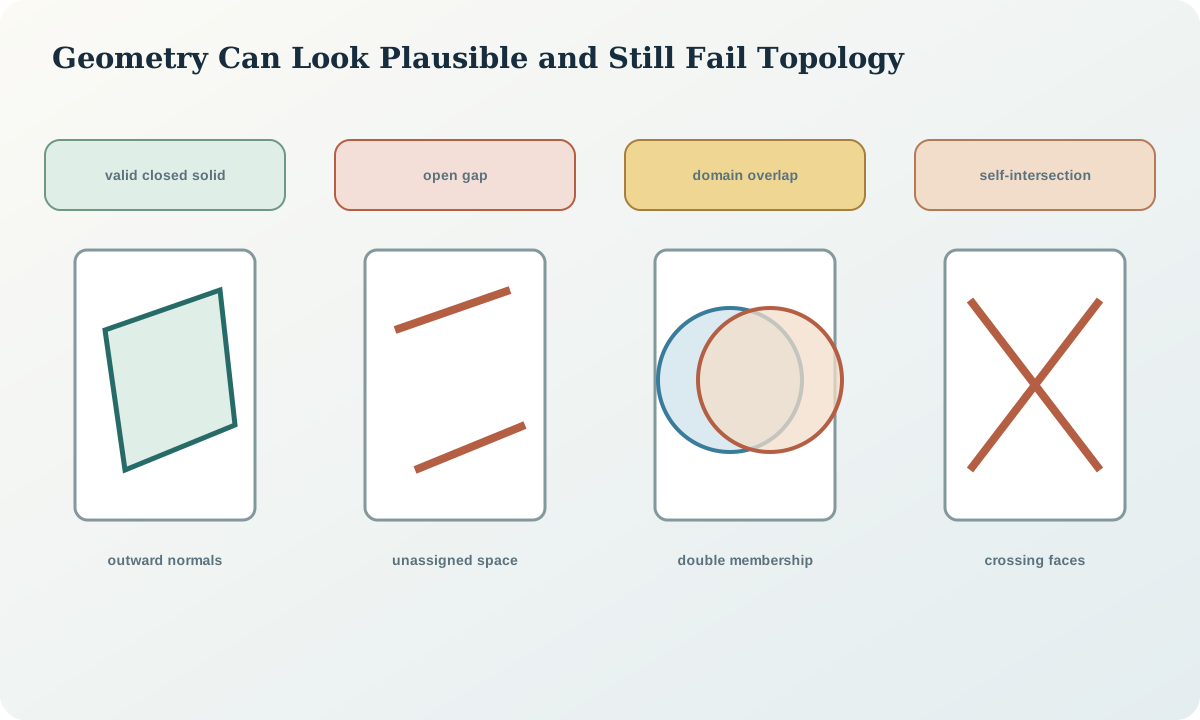
A valid shell should have no unintended boundary edges: each ordinary edge belongs to two faces in the shell. Face normals should point consistently outward. Non-manifold edges, where more than two faces meet, may indicate duplicate surfaces, unresolved junctions or a representation that cannot support standard solid operations.
Check connected components, duplicate faces, zero-area triangles, dangling vertices and isolated slivers. Signed volume can expose inverted orientation, but a positive total does not prove local correctness. Test each component and inspect junctions among contacts, faults and model bounds.
Self-intersections, gaps and overlaps
Self-intersection occurs when a surface crosses itself or when non-neighbouring faces intersect. It can arise from twisted correlations, excessive smoothing, fault displacement or poor triangulation. Repair should return to the generating constraints where possible; local mesh surgery can hide a geological contradiction.
Gaps leave space unassigned. Overlaps assign one location to multiple supposedly exclusive domains. Both may be smaller than display pixels but materially affect volume or coding. Test them numerically using tolerances appropriate to model scale and coordinate precision. Report tolerance-dependent results rather than declaring exact closure from rounded coordinates.
Adjacency and geological relationship tests
Derive an adjacency graph from the solids and compare it with the intended geological graph. If Unit 1 should never touch Unit 4 except across a named fault, any direct shared face is a defect or a new interpretation. Test containment of younger intrusions, truncation beneath unconformities and unit order within each fault block.
Topology also provides a compact comparison between scenarios. Two models may have similar volumes and contact residuals but different adjacency or connectivity. Those differences often matter more to a decision than small geometric shifts.
Repair, tolerance and audit trail
Classify repairs as numerical, representational or interpretive. Merging coincident vertices within a justified tolerance may be numerical. Adding a model-boundary cap is representational. Moving a fault so that two units no longer overlap is interpretive. Only the first two may be automated without geological approval, and even then the rule and affected objects should be logged.
Never run an opaque “repair all” operation on the only model copy. Preserve the pre-repair object, software-independent defect report, parameters and post-repair validation. A repair that changes volume, adjacency or contact residuals needs impact review.
Synthetic worked example
The fictional target solid renders as a continuous lens. Automated checks find one open ring at the lower boundary, six duplicate faces near a fault junction and a 0.8\,\mathrm{m} overlap with the surrounding unit. The open ring is closed with a tagged model-limit cap. Duplicate faces are removed after confirming they came from repeated export. The overlap traces back to incompatible fault displacement between two surfaces and cannot be fixed as a mesh-only operation.
Two displacement alternatives are rebuilt. One eliminates the overlap but creates an adjacency forbidden by stratigraphic order; the other preserves order and passes contact checks. The repair record shows that topology, not appearance, selected the acceptable interpretation.
Practice and review checklist
Run or design tests for a set of domain solids:
- shell closure and boundary-edge count;
- consistent face orientation and signed volume;
- duplicate, zero-area and non-manifold faces;
- self-intersection within and between objects;
- pairwise overlap and total unassigned volume;
- minimum sliver thickness and component size;
- adjacency graph against intended geology; and
- sensitivity to the chosen numeric tolerance.
For every repair, label it numerical, representational or interpretive and state whether geological review is required.
Decision implications and integration
Release a topology report with the solids. Include tests, tolerances, defect counts, repair actions, unresolved limitations and an adjacency graph. A file that opens without error is not a topology certificate.
Downstream domain coding should reference solid identifiers and a boundary ownership rule. Points exactly on a shared face require a deterministic convention. Voxelisation or block coding should then be validated against source volumes and thin-feature retention.
Sources
- Simple Feature Access, defines common geometry, boundary and validity concepts.
- Constraining stochastic 3D models with topology information, treats topology as a geological constraint and ensemble summary.
- GemPy 1.0, describes topology analysis for structural geological models.
- Three-dimensional geologic maps and visualization, links surfaces and interaction rules to geological volumes.