C6 · Publication Volume 16
Collar, Setup and Survey Control
collar position, azimuth, dip, rig alignment and surveying
Learning objectives
This lesson establishes the spatial origin of a drillhole. The learner should be able to define collar coordinates and datums, distinguish planned from set-up and final surveyed geometry, express azimuth and dip conventions, audit rig alignment, record uncertainty and decide whether the collar evidence is adequate for later trajectory reconstruction.
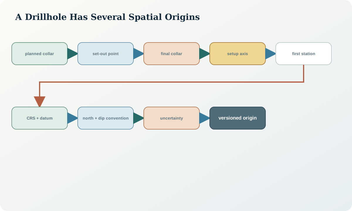
An accurate downhole instrument cannot repair an unidentified collar or unknown coordinate reference system. The collar, initial direction and survey conventions form one spatial observation. If any component is ambiguous, every interval inherits the ambiguity.
Persistent identity and planned geometry
Assign the hole identifier before field work and never reuse it, even if a hole is abandoned, redrilled or renamed for display. Relate parent and replacement holes explicitly. Keep the identity separate from mutable fields such as target name, program year, status or location description.
The planned collar record includes easting, northing, elevation, horizontal coordinate reference system, vertical datum, coordinate epoch where relevant, planned azimuth, dip, target depth, target volume, tolerance and design version. State whether the position is a point on the ground, top of casing, drill table, mast reference or another physical mark. A coordinate without its physical reference can be precisely wrong.
Planned azimuth requires a north reference. Grid, true and magnetic north are different. Declination and grid convergence are transformations with sign and date, not informal corrections. Planned dip requires a sign convention and reference plane. In this book, -60^\circ means sixty degrees below horizontal; another system may store inclination from vertical. Preserve the source convention and transform explicitly.
Field set-out and collar establishment
Set-out transfers the design to the ground. Record the set-out method, instrument or service, control points, coordinate reference system, operator role, time, stated uncertainty and any offset from the physical collar. Marking a point with handheld navigation may be adequate for reconnaissance but not for a narrow target requiring sub-metre control. Suitability depends on the decision tolerance.
Before setup, confirm hole identity, location, access, exclusion zones, services, topography, drainage and approved work area under the applicable field controls. Photograph the undisturbed site and established mark where authorised. Record relocation rather than silently editing the planned coordinate. A moved collar creates a new actual observation and may require target redesign.
The final collar survey should be independent of the planned value. Do not copy the plan into the actual field because the difference appears small. Record method, precision, datum, physical reference and whether elevation came from the same survey solution as horizontal position. Digital elevation-model height, ellipsoidal height and orthometric elevation are not interchangeable.
Rig alignment and initial direction
Rig setup aims the borehole along the approved initial line while providing stable, safe support for the equipment. Record the reference used to align the mast or feed frame, the points or targets observed, measured azimuth and dip, instrument identity, repeat readings and acceptance result. The physical line being measured must be defined; measuring a convenient steel edge that is not parallel to the drill axis introduces systematic error.
Magnetic alignment near steel plant, power sources or magnetic ground can be biased. Optical or inertial methods may provide alternatives, but each has line-of-sight, setup and calibration requirements. A compass agreement with the planned azimuth is not an independent check if the same disturbed magnetic field affects both readings.
Initial alignment and the first reliable downhole station should be compared. A difference may reflect setup error, early hole curvature, measurement uncertainty or reference conversion. Do not overwrite the setup reading to match the survey. Preserve both and investigate the mechanism.
Setup records and drilling events
The setup record should include hole identity; planned and actual collar; mast reference; measured initial azimuth and dip; method and diameter; casing; commencement time; coordinate and north conventions; alignment checks; responsible roles; and approval status. It should link to photographs and raw survey files without relying on filenames as identity.
During drilling, record events against measured-depth ranges: casing, method or diameter changes, bit and core-barrel configuration, significant losses, water observations, circulation changes, additives, stuck equipment, redrilling, wedges, sidetracks and termination. Event depths may have different uncertainty from sample depths; preserve the observation basis.
A sidetrack is not merely a note. It creates a branching geometry that needs a distinct identifier or branch key, a tie point, survey records and explicit sample association. Combining two physical paths under one unqualified depth axis makes later intervals spatially ambiguous.
Spatial uncertainty and quality controls
Construct a collar uncertainty statement from control quality, instrument performance, setup, transformation and physical-reference uncertainty. Do not report more coordinate decimals than the evidence supports. Precision of storage is not accuracy of location.
Useful controls include independent check coordinates, repeated setup angles, backsight or control closure, photographs showing the reference, comparison between plan and actual, and a signed convention sheet. Define thresholds by target geometry and decision consequence. A two-metre horizontal uncertainty may be immaterial for regional stratigraphy but decisive for a narrow structure.
Validate that coordinate ranges are plausible, eastings and northings are not swapped, elevation is consistent with local terrain and datum, azimuth falls in its declared range, dip obeys its sign convention, and actual collar does not equal planned collar by default across every hole. Identical plan and actual values are a signal to inspect, not automatic proof of error.
Synthetic worked example
A synthetic hole is planned at (428,250.00, 7,311,840.00, 612.4)\,\mathrm m in a declared projected system, at grid azimuth 126.0^\circ and dip -60.0^\circ. Field access requires moving the collar 3.2\,\mathrm m west and 1.1\,\mathrm m north. The set-out record retains the planned point and creates an actual set-out point; the target intersection is recalculated before setup.
Two independent final collar observations differ by 0.18\,\mathrm m horizontally and 0.09\,\mathrm m vertically. The adopted coordinate is stored with an uncertainty statement rather than simply averaging unexamined results. Rig alignment gives grid azimuths 125.6^\circ and 125.8^\circ, and dips -59.7^\circ and -59.8^\circ. The first downhole station at 12\,\mathrm m reads 126.3^\circ, -59.5^\circ. The difference is retained and marked for review after the next station.
If the actual collar had been overwritten onto the planned fields, the design change would disappear. If magnetic and grid azimuth had been mixed, an apparently small numerical difference could conceal a systematic rotation. The accepted record keeps plan, set-out, final collar, setup line and survey station as separate evidence.
Practice and review checklist
- Is the hole identifier persistent, unique and never reused?
- Are planned, set-out and final collar records separate?
- Are horizontal reference system, vertical datum, epoch and physical reference explicit?
- Are azimuth north reference, range and conversion recorded?
- Is dip convention unambiguous?
- Was the drill axis, rather than an undefined rig edge, measured?
- Were magnetic interference and independent alignment considered?
- Are method, casing, diameter, wedge and sidetrack events depth registered?
- Is coordinate uncertainty compatible with target geometry?
- Can raw observations be recovered without trusting a display export?
Any “actual” coordinate copied from the plan without an observation status should be quarantined. Any branch, redrill or relocated collar without an identity relationship should be resolved before samples are integrated.
Decision implications and handover
The collar and setup package is accepted when the physical origin, coordinate system, height reference, actual line, conventions, uncertainty and changes are reconstructable. It should hand the downhole survey team a stable hole identity, adopted collar, initial direction, north reference and expected interference conditions.
Later desurvey calculations must use the adopted version deliberately. If a collar is corrected after interpretation, all derived coordinates become candidates for regeneration. The correction is a new version with lineage, not an in-place edit. Geological conclusions should state whether their positional confidence is limited by collar or trajectory uncertainty.
Sources
- Applications of drilling, coring and sampling techniques, describes field establishment and drilling records in relation to investigation objectives.
- Exploration-activity reporting guide, requires collar, survey, drilling and related raw records in a public reporting setting.
- Borehole deviation measurement, explains inclination, azimuth and sources of magnetic measurement error.
- Geoscience information model, provides formal borehole geometry and coordinate-reference concepts.