C6 · Publication Volume 16
Downhole Surveying
measurement tools, frequency, magnetic interference and quality
Learning objectives
This lesson treats a downhole survey as a sequence of measurements rather than a finished trace. The learner should be able to specify station fields, distinguish tool families, select station spacing from curvature and target tolerance, recognise magnetic interference, evaluate repeats and plausibility, and preserve sufficient metadata for later trajectory calculation.
A rendered hole trace is a derived interpretation. The primary evidence is the collar plus measured-depth stations with azimuth, dip, reference, method, time and quality. Different interpolation algorithms can produce different coordinates between the same stations, especially when spacing is wide or curvature is high.
Station model and angular conventions
Each station needs hole identity, measured depth, azimuth, dip or inclination, timestamp, instrument identity, tool mode, calibration state, north reference, raw and corrected values where applicable, temperature or other relevant conditions, repeat group, quality flags and source-file lineage. Measured depth must refer to a defined tool point and depth system.
Azimuth is circular. A difference between 359^\circ and 1^\circ is 2^\circ, not 358^\circ. Dip conventions vary; store the source field and a normalised field with the transformation documented. North corrections must identify input reference, output reference, model or observation date and sign. Do not apply a correction twice because a file label is unclear.
The collar and a defensible initial-direction observation usually form the zero or near-zero geometry. A survey recorded at zero depth may be a copied setup value rather than a downhole measurement. Its observation type should make that distinction explicit.
Measurement tool families
Magnetic tools estimate direction relative to the local magnetic field and gravity. They can be compact and effective in suitable conditions but are vulnerable to steel casing, rods, nearby plant, magnetic minerals and local field disturbances. Quality records should include the configuration, stand-off from steel, field diagnostics and reason for accepting or rejecting a station.
Gyroscopic tools estimate orientation using inertial principles and can avoid magnetic-field dependence. They have their own alignment, drift, calibration, temperature and operating-mode uncertainties. North-seeking, reference and continuous modes should not be treated as interchangeable labels. The delivered output must be tied to the actual configuration and processing.
Optical, mechanical and borehole-imaging methods may contribute orientation or deviation observations under specific conditions. Tool choice depends on hole condition, diameter, casing, fluid, temperature, access, required accuracy and whether a retrievable check is possible. “Non-magnetic” does not mean “error-free.”
Station spacing, interference and plausibility
Choose station spacing from expected curvature, target width, intersection tolerance and instrument performance. Closely spaced stations reduce interpolation distance but can add little value if measurements are noisy and not independent. Wide spacing can hide doglegs and place an interval on the wrong side of a target. A fixed routine spacing may be supplemented around method changes, wedges, suspected deviation, target approaches and end-of-hole.
Survey design should specify initial check, routine interval, repeat policy, end-of-hole confirmation, pullback or independent survey where feasible, and response to a failed station. It should also specify how depth is referenced when the tool is conveyed inside rods or in an open hole.
Dogleg severity expresses change in direction per length, but the chosen calculation and units must be declared. A high value can represent true curvature, a bad station or an azimuth instability near vertical. Plot the raw angles, angular differences and derived spatial curvature together before deleting anything.
Magnetic interference and station plausibility
Inspect magnetic diagnostics where available, but do not rely on a single threshold divorced from local conditions. Steel proximity, remanent magnetisation, electrical equipment and magnetic formations can distort azimuth while dip remains plausible. Repeated biased readings can be precise but wrong.
Plausibility checks include angle range, circular change, dip behaviour, station-depth order, duplicate agreement, expected curvature, relationship to drilling method and comparison with an independent tool or survey direction. A sudden azimuth jump paired with abnormal field magnitude suggests interference; a gradual repeatable turn across several stations may be real.
Near-vertical holes have poorly constrained azimuth because a small horizontal component makes direction sensitive to noise. Flag the geometry rather than forcing an apparently exact azimuth. Near-horizontal holes can amplify vertical-position consequences of dip error over long distances.
Uncertainty and quality controls
Separate instrument uncertainty, alignment, depth, reference transformation and interpolation. Angular error accumulates into positional uncertainty with distance. Correlated bias, such as an incorrect north correction, does not average away with more stations. Report an uncertainty envelope or sensitivity, not only a centreline.
Useful controls include pre- and post-use calibration checks, repeat stations, check shots, diagnostic fields, comparison of run-in and pullback observations, independent tool sections, closure to a known direction where possible, and raw-file preservation. Define rejection and quarantine states. Never delete a suspect station from the primary record; exclude it from an adopted survey version with a reason and evidence.
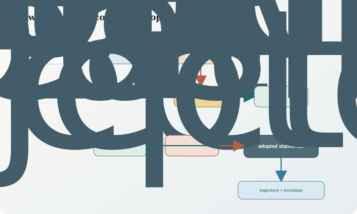
Version adopted surveys. The raw observation set, corrected set, accepted station set and derived trace are distinct entities. A later correction to one station should identify which traces, intervals, intersections and models are affected.
Synthetic worked example
A synthetic hole has stations at 0, 30, 60, 90 and 120\,\mathrm m. Grid azimuths are 042.0^\circ, 042.8^\circ, 043.7^\circ, 087.4^\circ and 045.6^\circ; dips are -65.0^\circ, -64.7^\circ, -64.3^\circ, -64.0^\circ and -63.5^\circ. The 90\,\mathrm m reading is a sharp isolated azimuth jump without a comparable dip change.
The raw record shows that the 90\,\mathrm m station was collected close to steel and has an abnormal field diagnostic. A repeat at the same depth after changing configuration reads 044.7^\circ, and a later independent run gives 044.9^\circ. The original value remains in the observation table with status “rejected—interference”; the accepted version uses the repeat and documents the evidence.
If the isolated value were used, the interpolated trace would make an artificial lateral excursion. If it were silently deleted, the trace might look correct but the audit trail would be broken. The defensible result includes both the failed observation and the adopted decision.
Practice and review checklist
- Does every station have hole identity, measured depth, angle conventions and north reference?
- Are raw and corrected angles preserved separately?
- Is the instrument and operating mode identified?
- Are calibration, field diagnostics and steel proximity recorded?
- Does station spacing match expected curvature and target tolerance?
- Are repeat, failed-shot and end-of-hole rules defined?
- Are circular angle differences calculated correctly?
- Are suspect stations quarantined rather than erased?
- Is the adopted station set versioned and linked to the raw file?
- Has positional sensitivity to angular and depth error been assessed?
The review should examine tables and plots. A smooth three-dimensional view can conceal a wrong north reference, copied station or unrealistic interpolation.
Decision implications and handover
An adopted survey is fit for use only for a stated purpose and tolerance. It may be adequate for regional geological correlation but inadequate for a narrow intersection or engineering design. Record that scope with the version.
The handover to logging and integration includes the adopted station set, rejected observations and reasons, collar version, conventions, interpolation method to be used downstream, uncertainty assessment and affected depth ranges. Geological contacts retain measured depth as their primary observation; derived coordinates can be regenerated when the survey changes.
Sources
- Borehole deviation measurement, summarises inclination and azimuth tools, magnetic limitations and gyroscopic alternatives.
- Considerations for drilling methods and borehole logging, explains how drilling and borehole conditions affect later measurements.
- Geoscience information model, formalises borehole geometry, interval coordinates and reference systems.
- Exploration-activity reporting guide, identifies collar and downhole survey data as required drillhole records.