C6 · Publication Volume 16
Structural Logging
alpha and beta angles, oriented core, feature types and confidence
Learning objectives
This lesson develops a traceable route from a feature on core to a geographic orientation. The learner should be able to define the core reference frame, measure alpha and beta angles, describe feature type and sense, evaluate orientation-line confidence, distinguish apparent from true orientation and reject structural measurements that lack adequate physical support.
Structural logging has two evidence layers: the feature must be correctly recognised, and the core must be correctly oriented. Mathematical conversion cannot compensate for an uncertain orientation mark, a rotated piece or a misclassified planar surface.
Core coordinates and reference frames
Define the local core frame before measuring. The core axis is the longitudinal direction. The orientation reference line establishes a zero direction around the circumference, with a declared view direction and clockwise sense. The top-of-hole and bottom-of-hole conventions must be explicit because viewing a circular cross-section from opposite ends reverses angular sense.
Keep four frames distinct: the physical core piece, the reconstructed run, the borehole axis at the feature depth and the geographic frame. Alpha and beta are core-frame observations. Borehole azimuth and dip place the core axis geographically. A rotation about the core axis connects the orientation line to a vertical or other reference. The final plane or line orientation is derived.
Store source angles and conventions alongside any converted strike, dip, dip direction, trend or plunge. A conversion should be reproducible from raw measurements, survey version and formula version. Do not retain only the geographic output.
Alpha and beta measurements
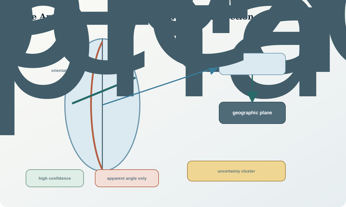
For a planar feature, alpha commonly expresses the acute angle between the plane and the core axis, while beta expresses rotation around the core relative to the orientation line. Conventions vary, so a diagram and worked physical check are mandatory. A plane parallel to the core axis and a plane perpendicular to it provide useful end-member tests for the chosen alpha definition.
Measure alpha on the trace of the plane along a suitable core surface or using a fitting device, acknowledging roughness and curvature. Measure beta only where the orientation line and feature can be connected on the same correctly reconstructed piece or through a defensible transfer. Record repeat readings and rounding.
Linear features require their own measurement model; they are not automatically handled as planar beta values. Intersection lineations, slickensides and mineral fibres may require trend within a plane, plunge on the surface or a three-dimensional vector. Define the observation rather than reusing a convenient field.
Feature description and orientation conversion
Describe feature type independently of orientation: bedding, foliation, cleavage, vein, fault surface, joint, fracture, contact or uncertain plane. Add morphology, thickness, roughness, waviness, infill, alteration, displacement indicators, cross-cutting relation and confidence. A geometric cluster of unlike features should not be treated as one structural population.
The conversion uses the borehole direction at the feature depth, not a collar azimuth copied to the whole hole. Interpolate the adopted trajectory according to a declared method. Rotate the local plane normal or line vector into the geographic frame and convert to the selected orientation convention. Test the implementation with known geometries and inverse transformation.
Planar orientation has a polarity ambiguity unless facing, younging, displacement sense or another directional indicator is observed. A plane can be represented by equivalent normal vectors of opposite sign. Do not infer stratigraphic facing from dip direction alone.
Uncertainty and quality controls
Structural uncertainty combines feature recognition, alpha reading, beta reading, core fit, orientation transfer, borehole survey and conversion. These terms can be strongly non-linear. When alpha is near an end-member geometry, small angle errors may create large azimuth changes. Report confidence or ensembles rather than false exactness.
Controls include repeated measurements, blinded remeasurement, physical reference pieces, convention checks, orientation-line continuity, comparison with borehole images, stereographic inspection, inverse calculation and audit of survey version. Plot measurements by feature type and confidence. A tight cluster can indicate shared systematic error just as easily as geology.
Quarantine observations with no orientation support, but retain alpha or apparent angle if it remains useful. “Unoriented” is not “no structural information.” It still constrains feature-to-core geometry and fracture frequency.
Synthetic worked example
A synthetic planar vein at 212.4\,\mathrm m is measured with alpha 38^\circ and beta 126^\circ under a documented convention. The orientation line is high confidence across the piece. The adopted borehole survey at that depth is grid azimuth 074.6^\circ, dip -57.2^\circ. Two independent readings differ by 2^\circ in alpha and 4^\circ in beta.
The conversion produces a geographic plane orientation, but sensitivity analysis varies alpha, beta and borehole angles within their observed uncertainty. The resulting normals occupy a small cluster rather than one exact point. A nearby fracture measured on a piece across an orientation gap is retained as apparent alpha only and excluded from the geographic cluster.
The conclusion states that the vein family is compatible with one model over the sampled interval, not that a single precise plane controls the entire structure. A second hole with a different intersection direction is proposed to test orientation bias.
Practice and review checklist
- Is the viewing direction, zero line and angular sense defined?
- Are alpha and beta meanings demonstrated with end-member geometry?
- Can the feature be linked physically to a valid orientation line?
- Is orientation confidence stored by depth rather than by hole?
- Is the feature type described independently of its angle?
- Does conversion use the adopted trajectory at feature depth?
- Are source angles, survey version and transform version retained?
- Are polarity and facing treated separately?
- Are repeats and inverse tests within expected tolerance?
- Can low-confidence data be filtered without deleting observations?
Reject a geographic orientation that cannot be reconstructed from raw core measurements and a named survey version. Reject structural populations assembled without separating feature type and confidence.
Decision implications and integration
Oriented-core data can constrain fold geometry, fault and vein sets, anisotropy and domain boundaries, but drillholes sample structures directionally. Features nearly parallel to the hole may be overrepresented in length or difficult to intersect; other orientations may be missed. Correct for observation opportunity before treating counts as population abundance.
Integrate structural measurements with photographs, geological intervals, recovery, orientation confidence and trajectory uncertainty. Publish both observations and derived orientations. A model should show whether its geometry is supported by high-confidence measurements, unoriented apparent angles, indirect correlation or interpretation.
Sources
- Engineering geology field manual—discontinuities, provides systematic description of discontinuity orientation, character and confidence-related observations.
- Geotechnical investigations manual, discusses oriented core, structural logging and borehole records.
- Standardized method for logging drill core, supports reproducible core description and photographic context for structural observations.
- Geoscience information model, supplies formal geometry, observation and borehole concepts for interoperable structural data.