C4 · Publication Volume 14
Borehole Geophysics
downhole probes, orientation, depth registration and calibration
Learning goals
The learner should be able to match a borehole log to its physical response and investigation radius; reconcile tool depth, borehole trajectory and sample depth; account for hole diameter, fluid, casing and motion; distinguish calibration from environmental correction; and integrate logs with surface observations without treating a one-dimensional trace as a complete property model.
Borehole measurements bring sensors close to the subsurface and provide continuous depth profiles, but the apparent precision of a plotted curve can be deceptive. Different tools sample different radial volumes, vertical supports and directions. A centimetre-scale depth mismatch can reverse correlations with narrow structures, while a borehole environment can dominate the response.
Log families and physical response
Natural gamma tools respond to gamma radiation around the hole; electrical and electromagnetic tools respond to formation and fluid conductivity over tool-specific volumes; density and neutron-type tools respond to scattering processes and require close attention to borehole condition; acoustic tools measure travel times, amplitudes or waveforms; calipers measure hole geometry; temperature and fluid logs describe the borehole fluid; optical or acoustic images map the wall with orientation where available.
No log is a direct lithology label. Natural gamma can vary with radioactive minerals, clay or alteration. Low resistivity can reflect fluid, clay, graphite or interconnected conductive minerals. Acoustic response depends on elastic properties, fractures, coupling and fluid. Interpret combinations through physical hypotheses and verify units and environmental corrections.
State whether a tool is passive or active, centralised or eccentred, contact or non-contact, continuous or station based, and whether the measurement is scalar, directional or image-based. Record tool serial identity, configuration, source–receiver spacing, sampling interval, logging speed, ascent or descent direction and raw channels.
Depth registration, trajectory and orientation
Depth on a logging cable is not automatically true vertical depth, drilled depth or geological sample depth. Cable stretch, wheel slip, winch calibration, tool length, surface reference, hole deviation and thermal effects can create offsets or scale errors. Declare the zero reference and preserve measured depth along hole separately from derived vertical elevation.
Use repeat passes and fixed reference features to estimate shift and stretch. Apply a versioned depth transform rather than overwriting raw depth. Core recovery, sample intervals and structural picks have their own depth uncertainties. Correlation should use interval overlap and uncertainty, not forced one-to-one matching.
Orientation requires a declared north reference, borehole trajectory and tool roll. Magnetic interference, acceleration and irregular hole shape can degrade orientation. Image-derived planes require the wall feature, tool orientation and hole deviation together. Show unorientable intervals rather than assigning a convenient azimuth.
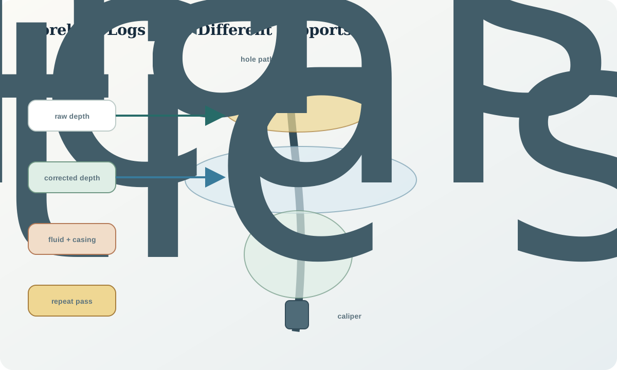
Borehole environment and corrections
Hole diameter, rugosity, fluid type, fluid conductivity, temperature, pressure, casing and tool decentralisation can alter logs. A caliper curve is therefore an interpretive companion, not merely a drilling record. Corrections calibrated for one diameter or fluid range should not be extrapolated without validation.
Casing can block, attenuate or redirect fields. An air-filled interval differs from a fluid-filled one. Drilling fluid invasion can make near-wall properties differ from undisturbed formation. Logging too quickly can blur vertical response or create motion noise. Record hole construction, fluid level and condition at logging time.
Environmental correction is a forward model with assumptions. Preserve raw and corrected channels, correction parameters and validity flags. If correction magnitude approaches the geological contrast of interest, report that limitation explicitly and seek a differently sensitive log or core property measurement.
Calibration, repeatability and cross-log correlation
Calibration links tool response to reference conditions; a functional check confirms operation before and after the run. Both are required. A stable tool can still be inaccurately calibrated, and a calibrated tool can fail during acquisition. Record reference facility or standard, date, coefficients, verification tolerance and drift check without implying endorsement by the source.
Repeat sections reveal depth shift, drift and local repeatability. Up- and down-logs can expose speed or direction effects. Cross-log correlation must respect different vertical and radial supports. Resample only after preserving native observations, and use kernels consistent with tool response rather than nearest-value convenience.
Tie logs to surface surveys through a forward relation. A downhole conductivity log can constrain an electromagnetic model; density can constrain gravity; susceptibility and remanence can constrain magnetics; velocity can constrain seismic depth conversion. A single hole samples one trajectory and should not be extended laterally without geological support.
Worked synthetic example
Two reliable reference features are observed at logged depths 100.0 m and 500.0 m, while independent references place them at 99.0 m and 497.0 m. Let corrected depth be z_c=az_l+b. Then
$a=\frac{497-99}{500-100}=0.995,$
and b=99-0.995(100)=-0.5 m. A feature at logged depth 300.0 m maps to z_c=298.0 m. This affine correction includes both offset and scale. It should be applied as a derivative column with tie points and residuals preserved.
Suppose the log's vertical response length is 0.8 m and a core interval is 0.25 m. Even after depth correction, a 0.20 m geological band cannot be expected to produce its full intrinsic log amplitude. Correlation must compare convolved support rather than interpreting the log minimum or maximum as an exact boundary.
Borehole-log audit workflow
- identify each tool's physical response, unit, radial and vertical support.
- reconcile tool configuration, source spacing, speed and pass direction.
- preserve raw cable depth, surface reference and trajectory survey.
- estimate depth shift and stretch from independent tie features.
- map diameter, fluid, casing, temperature and decentralisation effects.
- verify calibration and pre- and post-run functional checks.
- compare repeat and reciprocal passes in data space.
- correlate logs only after matching depth and support uncertainty.
- constrain surface models without extrapolating one hole as regional truth.
Practice and review
- Derive an affine depth correction from two tie pairs of your choice.
- Explain why a gamma log and a wall image can have different boundary depths.
- List environmental effects that could create an apparent conductive interval.
- Design a repeat-log test that separates depth shift from amplitude drift.
- State what is required to use a density log as a gravity-model constraint.
Review questions: What volume does the tool sample? Which depth reference is used? Is orientation reliable? Are environmental corrections within calibration range? Do repeat passes agree? How far can the borehole observation be extended laterally?
Sources
- Borehole geophysics applied to subsurface investigations, provides a primary manual of tool responses and interpretation.
- Borehole logging method table, relates common logs to measured properties, conditions and applications.
- Borehole geophysical logging protocol, documents depth, calibration, field procedure and reporting controls.