E1 · Publication Volume 23
Vertical Datums and Elevation
orthometric and ellipsoidal height, local reduced level and geoid models
Learning objectives
distinguish ellipsoidal height, orthometric or datum height, reduced level, depth and elevation fields; explain how vertical datums are realised; apply a declared separation model within scope; and reconcile national, project and engineering height networks.
The objective is transferable reasoning, not operation of a named product or performance of regulated survey work. Every real decision must use current applicable requirements, authorised control and competent review.
Decision context
The decision is which vertical reference controls each workflow and how values move between references without losing physical meaning. A national height datum, an ellipsoid, a local project benchmark, a mine reduced-level system, chart datum and depth below collar are different coordinate objects. Agreement in metres does not make them interchangeable.
The analyst defines a vertical hierarchy: authoritative external reference where required, project control realisation, local working grid, observation method, conversion model, adopted offsets, uncertainty, movement monitoring and release conditions. Real engineering control requires authorised survey governance beyond this tutorial.
Core concept
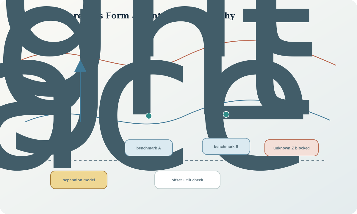
A vertical datum is realised through physical marks, observations, adjustments and conventions. Orthometric-style heights seek a gravity-related elevation; ellipsoidal heights are geometric; local reduced levels may be created by adopting an arbitrary or calibrated origin. Depth usually increases downward from a feature-specific origin and is not a height until converted through a declared trajectory and collar reference.
A separation model relates horizontal position to a vertical conversion for a named pair of systems. It has a resolution, coverage, version and uncertainty. A constant project offset can approximate a model only within demonstrated extent and tolerance; it must not escape into regional data as if it were a datum definition.
Reference frames and metadata
Vertical metadata includes vertical CRS or local-system identifier, datum realisation, benchmark identifier and status, height type, positive direction, unit, observation method, adjustment version, separation model and checksum, horizontal CRS used for lookup, adopted offset surface, coordinate epoch or observation time where relevant, uncertainty and validity extent.
A local benchmark value needs a tie to another reference or an explicit statement that no tie exists. Benchmark descriptions, witness marks and movement history are part of the coordinate evidence. A database field named RL must not be assumed to use the same origin across projects or time periods.
Quantitative reasoning
Under a declared h=H+N convention, H=h-N. A local reduced level can be written RL=H+\Delta_{local}(x,y,t), where the local offset may be a constant, fitted plane or more complex controlled surface. Its form and domain must be documented. For depth d positive downward from collar height H_c, a simple vertical hole illustration is H=H_c-d; deviated holes require the three-dimensional trajectory.
A levelling misclosure is distributed only under the adopted adjustment method and weighting. Do not close a loop by forcing one benchmark to agree when movement or gross error is plausible. Residual direction, route length, instrument setups and repeated occupation guide diagnosis.
Evidence and uncertainty
Evidence includes benchmark records, levelling observations, GNSS files, gravity-related model, local offset calibration, mine survey adjustments, instrument calibration, temperature and setup records, movement monitoring and independent check routes. A copied benchmark list without status dates may contain destroyed or moved marks.
Vertical error sources can be strongly correlated across nearby points because the same model, benchmark or setup is shared. A project-wide offset does not average away with more features. Report common systematic terms separately from per-point random terms.
Transformation and control
The controlled workflow assigns every Z-like field to a vertical type, quarantines unknowns, verifies benchmark status, computes only declared conversions, propagates uncertainty, tests independent marks and records the vertical operation separately from horizontal reprojection. Local control is recalibrated when anchor marks move or project requirements change.
Stop if the vertical datum is absent, the local origin cannot be recovered, a benchmark is suspect, a model is outside coverage, the horizontal lookup CRS is wrong, or the independent check suggests tilt or spatially varying bias. Do not repair vertical alignment with an unexplained constant nudge.
Interfaces and data
A robust schema uses separate fields for z_value, z_unit, z_positive, vertical_reference, height_type, origin_feature, benchmark, model, operation, uncertainty and status. Depth intervals retain measured depth and trajectory context; they are not replaced by derived elevations. Raster vertical units and vertical CRS belong in the delivery manifest.
Horizontal transformation services may ignore Z. Three-dimensional transformation services may expect ellipsoidal height rather than orthometric height. The interface contract declares accepted height type and reports whether Z was transformed, model-converted, offset, interpolated or passed through.
Integration checkpoint
The checkpoint passes when all vertical values in the synthetic project are classified, every conversion is linked to a named source and target reference, and an independent control tests both offset and tilt. Unknown Z fields remain blocked.
Ask whether a drillhole depth, terrain elevation, model block centroid and water level share a physical reference. If not, define the operations needed before comparison and the uncertainty each operation adds.
Synthetic worked example
A synthetic project has two stable benchmarks tied to a gravity-related datum, one disturbed benchmark, GNSS ellipsoidal heights, a local mine RL origin of 5000 m and a terrain raster with missing vertical metadata. A fitted local offset agrees at the two stable controls but the third residual differs by 0.18 m.
The learner marks the third benchmark suspect, does not bend the surface through it, and quarantines the terrain Z until its source is recovered. The 5000 m false origin is retained as a local convention, not presented as national height. All values are synthetic.
Practice task
Create a vertical reconciliation table for synthetic collars, terrain cells, water levels, level marks, block centroids and downhole intervals. Classify references, calculate one model conversion and one local-grid conversion, propagate uncertainties, and design an independent loop or control test.
Submit a vertical transformation graph, benchmark status map, residual-versus-location plot and interface contract.
Common failure modes
The following failures are treated as evidence or process defects, not cosmetic issues:
- treating depth and height as the same ordinate.
- calling local RL a vertical datum without its origin.
- using a constant offset beyond its calibrated extent.
- passing orthometric height into an ellipsoidal transformation.
- ignoring benchmark movement.
- forcing a surface through a gross error.
- assuming horizontal reprojection transformed Z.
For each failure, preserve the original evidence, identify its downstream reach, define a discriminating test and record whether the case is corrected, rejected or still unresolved.
Review questions
- How is a vertical datum realised?
- What distinguishes height, reduced level and depth?
- Why does a separation-model lookup require a horizontal CRS?
- How can residuals reveal tilt rather than a constant offset?
- Which vertical errors remain correlated across many features?
Answer with definitions, evidence, a calculation or test where relevant, and the condition that would reverse the conclusion. A product screenshot or unexplained code is not an answer.
Assessment artefact
The assessment artefact is a vertical datum and local-level reconciliation package. It includes type classification, benchmark governance, conversion surfaces, model resources, uncertainty and covariance terms, independent checks, blocked records, transformation graph and delivery schema. It authorises no real benchmark adoption or engineering level.
Sources and further reading
- GDA2020 Technical Manual, version 1.8, official technical definitions, formulae and worked computations; confirm the current version before operational use.
- AUSGeoid2020, official model scope, height relationship, coverage and uncertainty information.
- The Australian Geospatial Reference System, official overview of datums, reference frames, working surfaces and infrastructure.
- Australian Geospatial Reference System Compendium, official system-level context for reference frames, transformations and height surfaces.