A4 · Publication Volume 5
Strike, Dip, Trend and Plunge
orientation of planes and lines, right-hand rule and three-dimensional intuition
Learning objectives
After this lesson, you should be able to describe planes and lines, use an explicit right-hand-rule convention, test whether a line can lie within a plane and recognise common ambiguity in orientation data.
Orientations describe geometry, not origin
A bedding plane, fault surface or foliation can be approximated locally by a plane. A fold axis, mineral lineation, groove or intersection can be approximated by a line. Orientation records geometry only. It does not by itself prove which way was originally up, which block moved or which process formed the feature.
Plane orientation
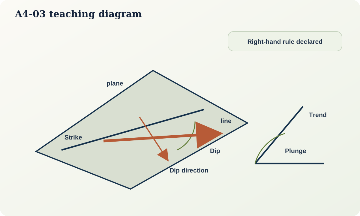
Strike is the azimuth of a horizontal line on the plane. Dip direction is the azimuth of steepest descent on the plane. Dip is the angle from horizontal down the line of steepest descent, from 0° to 90°. Strike and dip direction differ by 90° for a planar surface.
In the right-hand rule used here, the strike azimuth is chosen so the plane dips to the observer's right when looking along strike. The shorthand 035/48 therefore means strike 035° and dip 48° toward 125°. Other conventions exist. A dataset is incomplete unless it states which convention is used.
An alternative dip-direction notation records 125/48, explicitly giving the azimuth of dip. Never merge columns from the two notations without converting them.
Line orientation
Trend is the azimuth of the downward direction of a line. Plunge is the angle below horizontal, from 0° to 90°. A line trending 125° and plunging 32° may be written 125/32. For a horizontal line, direction may be bidirectional and should be documented. For a vertical line, trend is undefined or conventional; storing an arbitrary azimuth creates false information.
Measuring and checking
Before measuring, identify the physical feature and the surface on which it is observed. A rough outcrop may offer several local faces. Measure multiple parts, record dispersion and avoid selecting the value that best fits an expected map.
Basic checks include:
- dip is between 0° and 90°;
- plunge is between 0° and 90°;
- dip direction is approximately strike + 90° under the declared convention;
- a line believed to lie in a plane cannot plunge more steeply than the plane's true dip; and
- a line parallel to strike has zero plunge on an ideal plane.
Apparent dip
The slope of a plane seen in a vertical section is apparent dip unless the section is perpendicular to strike. If true dip is \alpha and the horizontal angle between section direction and strike is \theta,
\tan \psi = \tan \alpha\sin\theta
where \psi is apparent dip. If the angle is measured from dip direction instead, the cosine form is used. State which angle is meant.
For true dip 40° and a section 30° from strike,
\psi = \arctan(\tan 40^\circ \sin 30^\circ) \approx 22.8^\circ.
A section oblique to strike must therefore show a shallower angle than true dip.
Can a line lie in the plane?
Suppose a plane strikes 000° and dips 30° east. A line within it trending east has plunge 30°; one trending north has plunge 0°. Intermediate trends have intermediate plunge. A recorded east-trending line plunging 45° cannot lie in that plane within measurement tolerance. The inconsistency may indicate transcription error, measurement from different surfaces or an incorrect assumption that the line is contained in the plane.
Orientation uncertainty
Natural surfaces are irregular and folded. Report a representative value only with its spatial support. “Bedding 035/48” might describe a 10 cm patch or a 50 m limb; those are not equivalent. Useful records include number of repeats, range, surface roughness, instrument resolution and whether the value was measured directly or derived from points.
For folded beds, a mean orientation can be geologically misleading. Plot the individual values and inspect clusters or girdles before averaging.
Practical investigation
Use a stiff card as a plane. Draw a horizontal strike line, tilt the card and mark the dip line. Rotate a second vertical card through several section directions and trace the intersection. Measure apparent dip each time. Confirm that it is greatest perpendicular to strike and zero parallel to strike.
Then draw a line on the tilted plane. Measure its trend and plunge. Test whether the pair is geometrically possible using a stereonet or vector calculation.
Common failure modes
- Recording strike without dip direction or convention.
- Treating a vertical plane's two strike directions as different planes.
- Confusing trend/plunge with bearing/slope measured on a map.
- Measuring topographic slope instead of geological dip.
- Plotting true dip in an oblique section.
- Inferring movement sense from a lineation alone.
- Averaging orientations across two fold limbs.
Mastery check
- Convert right-hand-rule
210/55to dip-direction/dip notation. - What is the apparent dip of a 60° plane in a section 20° from strike?
- Can a line plunging 50° lie in a plane dipping 35°?
- Why is trend meaningless for a perfectly vertical line?
- What information should accompany a representative orientation from a rough surface?
Sources and further reading
- USGS, *Apparent Dip Calculator and Derivation*: https://pubs.usgs.gov/publication/tm7C28/full
- FGDC, *Digital Cartographic Standard for Geologic Map Symbolization*: https://ngmdb.usgs.gov/fgdc_gds/geolsymstd/download.php