A4 · Publication Volume 5
Outcrops, Contacts and Geological Boundaries
outcrop, contact, covered areas and boundary uncertainty
Learning objectives
After this lesson, you should be able to distinguish outcrop from float and subcrop, classify contact evidence, represent location confidence and avoid turning interpolation into an apparent observation.
What a contact line means
A geological contact is a boundary between mapped bodies or units under a declared classification. It may be sharp, gradational, intrusive, depositional, tectonic or uncertain. The line on a map is a representation of where that boundary intersects the mapped surface. The physical boundary may have thickness, irregularity and internal complexity below map resolution.
Exposure states
Outcrop is material exposed in place. Subcrop is bedrock close to the surface but not continuously exposed, inferred from shallow cover or excavation. Float is loose material displaced from its source. Regolith and transported cover may obscure bedrock while carrying fragments from upslope or upstream.
A map should not give float the same locational meaning as in-place exposure. Angular abundant float may constrain a source corridor, but the transport process, slope and drainage must be considered.
Contact evidence classes
A practical evidence vocabulary is:
- observed: the boundary itself is exposed and examined;
- accurately located: not necessarily exposed at every point, but constrained within the plottable tolerance for the map scale;
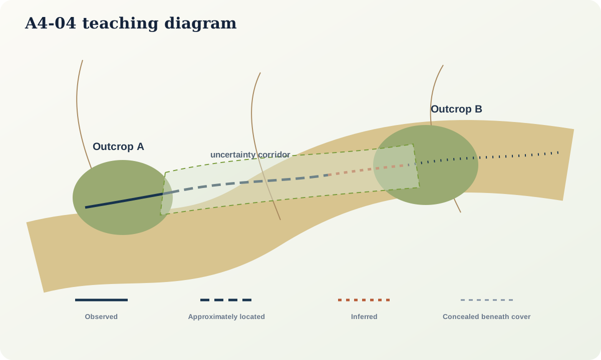
- approximately located: evidence constrains a broader corridor;
- inferred: continuation is proposed from indirect evidence or geological consistency;
- concealed: the feature is understood to continue beneath cover, water or another unit;
- queried: identity or continuity is doubtful.
Public geologic-map standards use combinations of solid, dashed, dotted and queried line symbols to communicate these states. Always follow the map's legend because exact styling varies. The scientific principle is stable: line style carries evidential meaning, not decoration.
Mapping a diffuse transition
Suppose sandstone becomes mudstone through a 35 m interbedded interval. A unit boundary might be defined at first persistent mudstone, at 50% mudstone or at a biostratigraphic marker. None is naturally the only “true” line. The mapper must state the criterion and represent the transition width where relevant.
If the criterion can be located within ±8 m, a crisp digital line still represents that uncertainty. At small scale the interval may be too narrow to show; the legend or metadata must preserve the rule.
Interpolating between outcrops
Two contact observations do not uniquely determine the path between them. Interpolation may use topographic expression, orientation measurements, geophysical patterns, unit thickness and nearby exposure. Each additional constraint narrows alternatives but does not convert the connecting segment into direct observation.
At Open Ridge, a contact is observed at stations 014 and 019, 420 m apart. Bedding is consistent at 060/25 southeast. The topography is gentle and the unit maintains thickness nearby. A smooth connecting trace is reasonable, but a small fault or fold could remain undetected. Map the observed segments as solid and the intervening segment with the style for approximate or inferred location; record the supporting assumptions.
Contact–topography interaction
The map trace of a plane depends on orientation and relief. A horizontal contact follows a contour. A vertical contact is comparatively insensitive to elevation and tends to trace straight across relief. A dipping contact bends across valleys and ridges. The familiar “V rule” is not a single memorised direction: the shape depends on dip magnitude relative to valley gradient and flow direction.
Use a three-dimensional construction or structure contours when the relation matters. Do not infer dip direction from a valley V without checking topography and possible overturned beds.
Faults and contact displacement
An offset map trace does not automatically reveal fault slip. Apparent offset depends on fault orientation, displaced surface orientation and erosion level. Establish that the two segments represent the same marker, map the fault trace, look for kinematic indicators and consider three-dimensional geometry. State observed separation on the map before interpreting displacement.
Practical investigation
On a transparent sheet over a topographic base, plot six synthetic outcrop polygons representing two units. Draw three alternative contact traces that all satisfy the observations. For each trace, write one additional observation that would reject it. Then assign observed, approximate, inferred and concealed styles and create a legend.
Common failure modes
- Treating all loose fragments as local bedrock.
- Drawing a continuous solid contact through covered ground.
- Hiding a gradational zone behind an unexplained crisp line.
- Letting an old map override contradictory new observation without review.
- Inferring fault motion from map separation alone.
- Applying a simplified valley rule without comparing dip and valley slope.
- Using colour boundaries without line-style evidence categories.
Mastery check
- What distinguishes an observed contact from an accurately located contact?
- How should a 35 m transition be represented on a 1:100,000 map?
- Why do two contact observations permit multiple connecting traces?
- What controls the V shape of a contact across a valley?
- What evidence is needed before map separation becomes a displacement interpretation?
Sources and further reading
- USGS, *Field Description of the Scientific and Locational Accuracy of Geologic Features*: https://pubs.usgs.gov/of/2002/of02-370/soller1.html
- FGDC, *Geologic Map Symbol Standard*: https://ngmdb.usgs.gov/fgdc_gds/geolsymstd/download.php
- USGS, *Geologic Data Assistant*: https://pubs.usgs.gov/of/2004/1451/haugerud/