A4 · Publication Volume 5
Block Diagrams and 3D Geological Geometry
block diagrams, surfaces, volumes and intersections
Learning objectives
After this lesson, you should be able to relate map traces to surfaces, interpret intersections among planes and volumes, construct a consistent block diagram and recognise perspective distortion.
Three linked views
A map shows the upper surface of a geological model. A section shows its intersection with one vertical plane. A block diagram shows selected faces and often a cutaway top. These are not separate stories. A valid model must produce compatible traces in every view.
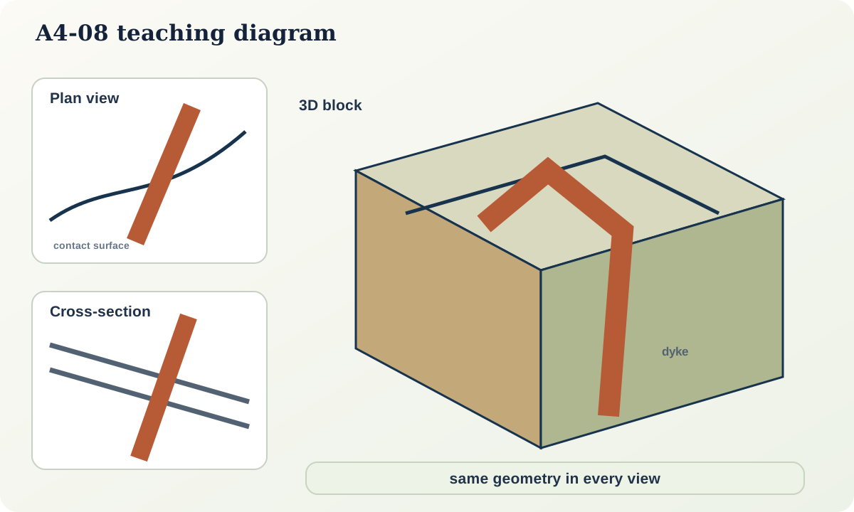
Surfaces, volumes and intersections
A contact surface separates two volumes. Where it meets topography it creates a map trace. Where it meets a section plane it creates a section line. Two non-parallel planes intersect in a line. A fault displacing a contact changes the contact's intersection geometry on both sides.
Thinking in intersections prevents a common error: copying a map line down the vertical face of a block without accounting for dip. The side-face trace is controlled by apparent dip relative to that face.
Building a block diagram
- Draw a rectangular block with a horizontal top and two vertical faces.
- Transfer topographic or map traces to the top at a consistent scale.
- Choose face directions and convert orientations to apparent dip on each face.
- Extend contact surfaces through the block, preserving topology and declared thickness assumptions.
- Add faults or intrusions in relative-age order.
- Remove hidden lines or show them transparently with an inference style.
- Check that the top reproduces the map and each face reproduces the corresponding section.
Perspective drawings are visually useful but poor measurement surfaces. Use an orthographic or explicitly scaled construction for quantitative work.
Structure contours
Structure contours connect points of equal elevation on a geological surface. For a plane, they are straight, parallel and perpendicular to dip direction. Their spacing s relates to contour interval h and dip \alpha:
s=\frac{h}{\tan\alpha}.
For 20 m structure-contour interval and 30° dip, spacing is about 34.6 m. Intersecting structure contours of a contact with topographic contours of the same elevation locates the outcrop trace. This method makes the three-dimensional relation explicit.
Faulted geometry
A fault is also a surface. The line where it intersects topography is not the same as its subsurface position. To show separation, first construct the pre-fault contact surface, then apply displacement or reconstruct corresponding points. Without kinematic evidence, a block diagram may show map separation but should not invent a slip vector.
Folds and curved surfaces
Curved surfaces require more than one orientation. Map a set of tangent measurements and infer a continuous surface that honours them. On a cylindrical fold, bedding orientations vary around an approximate fold axis. A block diagram should show the curvature rather than joining limbs with an arbitrary sharp corner unless a kink geometry is supported.
Hidden geometry and uncertainty
Use transparent envelopes, alternative panels or dashed hidden traces. Transparency alone can become visually confusing, so pair it with a legend. The model boundary should stop at the region of useful constraint rather than fill the block by default.
Practical investigation
Create a cardboard block with a removable top. Draw a dipping contact on an internal sheet and cut the sheet to the block. Trace where it meets the top and sides. Rotate the contact and observe how each trace changes. Add a second plane and mark their intersection line.
Then reverse the exercise: use the three face traces to infer the internal plane. State whether the solution is unique.
Common failure modes
- Treating a perspective face as a true-scale section.
- Copying map traces vertically down block faces.
- Drawing incompatible contacts on adjacent faces.
- Showing fault separation as a known slip vector.
- Using one orientation to define a strongly curved surface.
- Rendering inferred geometry as opaque fact.
- Filling an entire block beyond data support.
Mastery check
- What creates a map trace of a contact?
- Why is the line on a block face an apparent dip?
- Calculate structure-contour spacing for 10 m interval and 45° dip.
- What must be known before map separation becomes slip?
- How can three views be used to audit one another?
Sources and further reading
- USGS, *Digital Geologic Cross Sections*: https://pubs.usgs.gov/of/2005/1428/thoms/index.html
- OGC, *GeoSciML 4.1*: https://www.ogc.org/standards/geosciml/