C2 · Publication Volume 12
Survey and Sampling Design
purpose, scale, orientation, density, representativity and cost
Learning goals
After this lesson, you should be able to derive survey design from a decision question, use orientation work to estimate footprint and noise, choose support, direction and spacing relative to expected geometry, distinguish representativity from analytical precision, and specify quality controls and adaptation rules before acquisition.
A survey is an observation system, not a grid laid over a map. Its design includes the target population, measurement support, selection rule, spatial and temporal geometry, preparation, analysis, quality control, detection performance and interpretation rule. A dense but biased survey can be less informative than a sparse design that samples the right population.
Decision question, population and measurand
Define the decision first. Are observations intended to detect a regional footprint, discriminate two structures, estimate local variability, locate a boundary or test a necessary absence? Each question implies a different population and acceptable error. A sample should be described by what material and support it represents, not only where its centre point lies.
The measurand is the quantity intended to be measured. For a soil program it might be element concentration in a declared horizon and size fraction over a particular support. For a physical survey it may be a field response after a specified correction. If the measurand changes between lines, seasons, crews or laboratories, the combined dataset does not represent one population without a transformation model.
Selection can be probability-based, systematic, stratified, adaptive or purposive. Systematic designs offer regular coverage but can alias periodic geology. Stratification can allocate observations across regolith, lithology or access domains. Purposive samples are valuable for characterising features but cannot be treated as unbiased estimates of a region. Record the selection probability or rationale.
Orientation survey and pilot learning
An orientation survey tests the observation system before full deployment. It examines sample medium, horizon or depth, particle size, support mass, direction, spacing, preparation, analytical method, detection limits, background populations, seasonal effects and expected signal-to-noise behaviour. It should include known contrasting geological settings where possible without using target labels to tune the final evaluation set.
Orientation asks whether the proposed method can detect the footprint at the intended scale and distinguish it from nuisance processes. A method that detects a signal only in one moisture state or regolith unit needs a domain-specific design. If background variance overwhelms the expected contrast, closer spacing alone may not solve the problem.
Set adaptation rules before expansion. Examples include tightening spacing where adjacent observations show a reproducible gradient, changing medium after a declared quality failure, or stopping a method when duplicates show unacceptable heterogeneity. Unrecorded field improvisation can create selection bias even when geologically sensible.
Geometry, spacing, direction and support
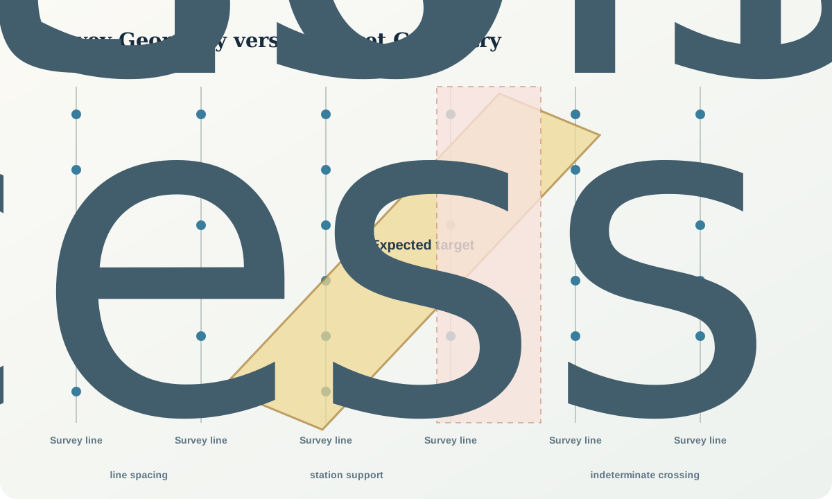
Lines should cross the predicted long axis or structural trend where the objective is to detect a narrow feature. If line direction is nearly parallel to the feature, a regular grid may miss it or exaggerate continuity. Use competing geometries to test whether the design remains adequate when orientation is uncertain.
Spacing is linked to the smallest footprint that the gate requires detecting, not to aesthetic map density. A simple deterministic rule might require at least two independent lines across the minimum target length and multiple observations across expected width. Real detection probability also depends on location phase, continuity, noise, support and processing.
Support changes variance and dilution. A large composite can smooth nugget effects but dilute a narrow anomaly. A small grab can capture extreme material but poorly represent the population. For particulate material, particle size, liberation and mass determine fundamental sampling variability. Sampling error occurs before laboratory analysis and cannot be removed by a highly precise instrument.
Representativity, QA and QC
Representativity means fitness of the selection and support for the target population; it is not a property guaranteed by sample count. Coverage bias, inaccessible sites, preferential sampling of visible alteration, recovery loss and transported material can shift the sampled population. Map deviations from the design and their causes.
Quality assurance defines the planned system; quality control produces evidence about its performance. Field duplicates include local heterogeneity plus field sampling. Preparation duplicates examine later subdivision. Analytical repeats estimate instrumental or analytical repeatability. Blanks test contamination; reference materials test accuracy and drift on a suitable matrix and concentration range. These controls answer different questions.
Randomise or balance sample order where sequence effects matter. Preserve blind identifiers when feasible and safe. Predeclare acceptance criteria and response actions: investigate, qualify, reanalyse, resample or reject a batch. A control failure does not automatically invalidate every result, but it must not be hidden or corrected without trace.
Worked synthetic example
A fictional linear footprint is expected to be 240 m wide, but orientation is uncertain by ±20°. The proposed survey uses lines normal to the preferred strike, 300 m apart, with observations every 60 m. Along an ideally oriented line, the footprint spans four intervals and is likely to be represented by about four or five observation locations depending on grid phase.
If actual strike differs by 20°, the apparent crossing width along the line is 240/\cos20^\circ\approx255 m. Station support remains adequate, but line spacing controls whether a short footprint is intersected. If the minimum target length along strike is 500 m, a 300 m line spacing can intersect it with one or two lines depending on phase. A gate requiring confirmation on two independent lines is therefore not guaranteed.
Reducing line spacing to 200 m provides at least two and commonly three crossings for a 500 m continuous target under the bounded geometry. That does not establish detection probability if the response is intermittent. The orientation program must estimate continuity and background variance. The design record should state: 200 m line spacing, 60 m stations, cross-strike orientation with ±20° scenario, two-line confirmation rule, and an indeterminate result if access removes a critical crossing.
Interpretation workflow
- Define the decision, target population, measurand and required detection scale.
- State competing footprint geometries and nuisance processes.
- Run orientation work across relevant geological and surface domains.
- Select medium, support, direction, spacing and method from observed performance.
- Model grid phase, orientation uncertainty and access gaps.
- Specify sample selection and record every deviation.
- Design field, preparation and analytical controls for their distinct purposes.
- Predeclare acceptance criteria, batch actions and adaptation rules.
- Preserve chain of custody, preparation lineage, qualifiers and raw results.
- Evaluate whether negative coverage had adequate detection power.
Practice and review
- Compare a 20 m composite with four 5 m samples for a predicted 6 m-wide feature.
- Design an orientation survey across residual and transported cover without mixing their backgrounds.
- Explain why analytical repeats cannot estimate field sampling heterogeneity.
- Test whether 400 m line spacing can satisfy a two-line rule for a 650 m-long target under all grid phases.
- Write a field adaptation rule that does not allow crews to chase unverified visual anomalies selectively.
Sources and further reading
- Measurement uncertainty arising from sampling, treats sampling and preparation as part of measurement uncertainty.
- Guidance on systematic planning using data quality objectives, links data type, quantity and quality to a decision.
- Sampling for Analytical Purposes, develops representativity for particulate materials.
- Practical applications of QA/QC in mineral exploration, reviews quality controls and their interpretation.