D4 · Publication Volume 20
Open-Pit Fundamentals
benches, ramps, phases, slopes and haulage
Learning objectives
By the end of this lesson, the learner should be able to read a basic open-pit design; distinguish bench, berm, inter-ramp sector, ramp, phase and ultimate limit; relate geometry to equipment and ground domains; explain stripping and phase logic; identify drainage, traffic and survey interfaces; and review a conceptual pit section without treating generic dimensions as design rules.
Design objects and their hierarchy
An open pit is a sequenced excavation, not an inverted cone. The smallest recurring design objects are bench faces, catch or working berms and floor elevations. Multiple benches form an inter-ramp sector; sectors are separated by ramps or wider berms and combine into overall walls. Phases or pushbacks create mineable intermediate shells with access and working room. The final limit is an economic and technical boundary, not necessarily the geometry exposed at any one time.
Give each object a stable identifier and version. A slope angle is meaningless unless its scale is named: bench-face, inter-ramp or overall. A line on a plan may represent crest, toe, design limit, as-built breakline or exclusion boundary. Store object type and elevation explicitly so that visually similar polylines are not exchanged as though equivalent.
Bench geometry and operating scale
Bench height interacts with geology, drilling and blasting, equipment reach, selectivity, survey resolution and statutory requirements. Berm width interacts with rockfall catchment, drainage, access and wall angle. Bench-face orientation can change the daylighting of discontinuities even where rock quality is uniform. Therefore, dimensions are designed by domain and function rather than copied from another pit.
Operational benches may be subdivided into mining flitches. Geological and grade-control support should match the decision thickness. A thin material band may be visible in a face yet lost when drill pattern, blast movement, loading selectivity and floor control are coarser. The design review must connect nominal geometry to actual excavation capability.
Ramps, roads and access continuity
A ramp is part of a connected transport and emergency system. Its width depends on vehicle envelope, lanes, windrows or barriers, drains, shoulders, clearance, stopping and passing arrangements. Gradient, curvature, sight distance, superelevation, surface condition and intersection design affect safe capacity. This tutorial supplies no universal dimensions; the design basis must use the selected equipment, applicable requirements and site conditions.
Track ramp continuity through every phase. A geometrically attractive wall can strand a lower phase, remove an escape route or create a narrow pinch point. Test inbound and outbound flows, disabled equipment, water accumulation, construction sequence and simultaneous work. Preserve survey control and communications coverage as walls advance.
Phases and working room
Phases distribute stripping, access and ore exposure through time. A valid phase must be geometrically nested where required, provide sufficient working width, maintain ramps and drains, expose practical drilling and loading faces, and respect geotechnical sectors. Narrow phases may improve nominal value timing while producing unachievable congestion or unsafe interactions.
Represent minimum width normal to the active face, not as a convenient horizontal map distance. Model the space needed for drill setup, blast exclusion, loading, spotting, road construction, scaling, dewatering and monitoring. Schedule interactions between adjacent elevations because vertical separation alone does not remove rockfall, flyrock or equipment exposure.
Slope domains and structural control
Divide walls into sectors using orientation, lithology, alteration, weathering, discontinuity geometry, strength, groundwater and excavation history. The design must distinguish structurally controlled bench-scale failure from rock-mass or composite inter-ramp failure. A discontinuity set that is benign in one wall orientation may daylight in another. Faults and weak seams can connect several benches.
Carry data confidence into the sector model. A smooth surface fitted through sparse orientation data can imply false continuity. Use structural scenarios, uncertainty corridors and exposure mapping. Update the domain after each new bench if mapped conditions, water or performance differ from the design basis.
Drainage, groundwater and weather
Separate surface runoff, perched water, regional groundwater, process water and incident water. Surface controls keep clean and contact water apart where required, limit erosion and prevent uncontrolled crest inflow. Pit sumps and pumps manage collected water; depressurisation targets pore pressure in slope materials. These systems serve different purposes and need independent monitoring.
Review storm storage, pump outage, blocked drains, sediment, freezing or intense heat where relevant, and the interaction between dewatering and slope response. Water-level readings need screened interval, datum and time. A wet wall observation is evidence of discharge at that location, not a complete hydraulic model.
Haulage, material movement and interfaces
The excavation sequence creates material streams. Each design parcel needs material class, destination rule, swell or volume basis, density and time validity. Haul profiles influence fleet capacity, fuel or energy, road maintenance and exposure. Stockpiles, crushers, waste facilities and construction sources constrain routing beyond the pit crest.
Connect design solids to surveyed movement and destination events. A phase plan can be spatially correct but fail if route capacity, dumping sequence or material blending is ignored. Distinguish design tonnes, blasted inventory, surveyed excavation and dispatched mass; they are not interchangeable.
Survey, monitoring and conformance
Establish control outside expected disturbance, transfer it with redundant observations and protect vertical datum. Survey design crests, toes, floors, ramps, drains and exclusion features at a resolution suited to their decision. Compare as-built geometry to the correct version and time. A point-cloud difference may combine real excavation, vegetation, water, occlusion and registration error.
Monitoring may include visual mapping, prisms, radar, extensometers, piezometers or other instruments chosen for the failure model. Define baseline, precision, sampling interval, data latency, trigger logic and response before movement occurs. No single instrument proves stability; observations test a model and controls.
Uncertainty and change control
Keep three envelopes separate: geological boundary uncertainty, engineering performance uncertainty and construction tolerance. When a wall exposes unexpected structure or water, quarantine the affected design object, map the observation, assess consequence, update the domain or scenario and obtain the required review. Do not silently edit a crest line so that the design appears to match the excavation.
Changes in ramp location, wall angle, phase width or floor elevation propagate to reserves, schedule, drainage, ventilation of deep pits, survey control and emergency arrangements. A change record names affected objects and the checks required before release.
Synthetic worked example
A synthetic western wall has four 15 m benches. The base model assigns one uniform inter-ramp sector, but new mapping on the second bench identifies a persistent clay-coated set dipping toward the excavation. Two piezometers also show head responding rapidly to rainfall in the same corridor. The next phase would place a ramp beneath this sector.
The review does not calculate a new slope angle. It splits the sector, adds a structural uncertainty corridor, relocates a temporary working boundary, requires drainage and kinematic assessment, and protects an alternative ramp alignment. The schedule marks the lower cut as conditional. Survey and monitoring teams receive the same sector identifier and trigger geometry.
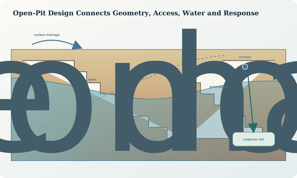
Practice and design-review record
Annotate a synthetic pit section with bench-scale, inter-ramp and overall objects; two access dependencies; a water pathway; and an uncertain structure. List the evidence required before the next phase advances. Then write a design-review record with source surfaces, design version, coordinate system, sector assumptions, equipment basis, conformance tolerance, monitoring status, deviations and release conditions.
A passing review distinguishes conceptual screening from approved design, reports no borrowed universal dimensions, and sends geotechnical, survey, water and operational questions to the roles authorised to resolve them.
Sources
- Planning safe excavations, WorkSafe New Zealand.
- Code of practice on safety and health in opencast mines, International Labour Organization.
- Ground control for Western Australian mining operations: code of practice, WorkSafe Western Australia.
- Mining and ground falls, National Institute for Occupational Safety and Health.