D4 · Publication Volume 20
Underground-Mining Fundamentals
access, development, stopes, support and backfill
Learning objectives
By the end of this lesson, the learner should be able to read a simple underground mine topology; distinguish access, development, production, support and backfill functions; compare broad stoping and caving families; identify ventilation, water, survey and emergency dependencies; reason about sequence and exposure; and prepare a conceptual layout review without authorising an excavation.
Underground topology and naming
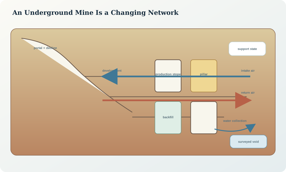
Underground geometry is a connected network with direction, capacity and state. Primary access may be a decline, shaft or adit. Levels and sublevels organise elevation; drives, crosscuts, raises and ore passes connect functions; stopes or panels are production excavations; chambers house services; escapeways and return airways carry critical safety functions. Local terminology varies, so the data dictionary must define every type.
Represent openings as solids or attributed centreline-and-profile objects, not only polylines. Record design, excavated, supported, unavailable, backfilled and sealed states with effective times. Connectivity must reflect doors, barricades, collapsed areas and one-way constraints. A visually connected plan can be operationally disconnected.
Access, development and lead time
Development creates the pathways required before production. Its sequence must establish safe access, ground support, ventilation, drainage, power, communications, materials handling and survey control. Advance rate depends on the complete cycle—mark-up, drilling, charging, exclusion, firing, re-entry, ventilation clearance, scaling, support, loading, services and survey—not only metres drilled.
Development ahead is an inventory with quality. Headings in the wrong location, profile or sequence may not create usable production fronts. Track metres by purpose, conformance, support status and service readiness. Protect alternatives where geological or ground uncertainty could interrupt a single access path.
Production-method families
Open stoping removes mineralised material while relying on stable spans, pillars and sequencing, sometimes followed by fill. Cut-and-fill or other supported methods advance in smaller increments while placing engineered fill or support. Room-and-pillar methods leave systematic pillars. Caving methods induce controlled rock-mass failure and flow. Each family has different geometry, selectivity, exposure, development, subsidence and monitoring requirements.
Avoid method labels without parameters. “Long-hole stoping” does not state stope dimensions, drilling accuracy, slot strategy, blast sequence, mucking, fill exposure or dilution controls. “Caving” does not state caveability, draw control, airgap, surface consequence or propagation monitoring. The design basis must make the mechanism explicit.
Stopes, pillars and extraction sequence
Stope stability depends on span, orientation, shape, rock mass, structures, stress, blast damage, time and neighbouring voids. Pillars transfer and concentrate load; they are engineered components rather than unmined leftovers. Sequence alters confinement and stress path, so analysing each stope alone can miss system behaviour.
Use a sequence graph with precedence, exclusion and curing constraints. Include primary and secondary stopes where relevant, retreat direction, sill or crown pillars, adjacent fill state and re-entry rules. Surveyed overbreak and underbreak update exposure geometry, but any design change needs geotechnical review.
Ground support and reinforcement
Reinforcement mobilises the rock mass, while support can retain or carry loosened material; many systems combine both. Bolts, cables, mesh, straps, shotcrete, sets and yielding elements have different load, displacement, corrosion, installation and quality requirements. A support pattern is inseparable from excavation profile, timing, ground domain and expected failure mode.
Record installed identity, location, orientation, length, type, batch, installation time, tests, damage and inspection. Design support, installed support and verified support are different states. Unexpected ground requires a controlled response, not informal addition of components whose interaction is unknown.
Backfill as an engineered system
Backfill may provide regional confinement, local wall support, working platform, disposal route or sequence enablement. Its required strength, stiffness, drainage and exposure time depend on function. Source material variability, binder, water, mixing, delivery, segregation, barricades, curing and quality testing affect performance.
Maintain a fill parcel ledger linking recipe, plant measurements, delivery destination, placed volume, sampling and exposure approval. Survey the void and placed fill on compatible bases. A nominal recipe does not prove in-place performance, and fill cannot be assumed to replace every pillar or support function.
Ventilation, water and services
Development changes the ventilation network continuously. Fresh and return paths, auxiliary ventilation, doors, regulators and stoppings must match active headings and contaminants. Water flows toward sumps and pump stations but can also follow structures, service holes or old workings. Power, communications, compressed air, fuel and backfill lines share constrained openings and require protection.
The layout review should trace failure of one fan, pump, substation, communications link or access. Identify single points of failure and isolation boundaries. Services geometry must use the same surveyed opening state as planning; a design centreline is not proof that clearance exists.
Survey control, voids and conformance
Transfer control underground through redundant networks suited to constrained geometry. Observe breakthrough, shaft or raise connections independently. Survey brows, walls, floors, stopes, raises, fill and inaccessible voids using methods appropriate to visibility and hazard. Mark unobserved surfaces and interpolation; a closed mesh can conceal large unseen regions.
Conformance compares the intended excavation with the realised void at the correct time. Register point clouds, scans and conventional observations to controlled coordinates and retain raw evidence. Volume difference must account for occlusion, water, broken inventory and the design reference used.
Exposure, re-entry and operational state
An opening can be spatially present yet unavailable because of firing, fumes, unsupported ground, rehabilitation, water, seismic response, equipment interaction or another exclusion. Operational state must be time-aware and communicated to schedules, dispatch, survey and geology. Do not encode access only as a note on a drawing.
Re-entry criteria should be measurable where possible: ventilation clearance, gas readings, ground inspection, support completion, seismic or monitoring response, barricade status and authorised release. The tutorial does not specify thresholds; applicable rules and the site control plan do.
Synthetic worked example
A synthetic narrow, steep body is divided into six longitudinal stopes accessed from a footwall drive. A weak cross-structure intersects stopes 3 and 4, and a high-head fracture domain lies beyond the eastern abutment. The initial sequence extracts alternating stopes, but development survey reveals the footwall drive is 4 m closer to the weak structure than the design model.
The interface review pauses the affected crosscut, preserves access to stopes 1 and 2, creates an alternative structural scenario, checks probe-drilling and drainage needs, and requires a revised ground-support and sequence assessment. The as-built drive, not the design line, becomes the geometry for ventilation, stress and emergency review. No support pattern is prescribed by the geology team.
Practice and layout-review record
Build a node-and-edge diagram for a small underground layout. Mark production fronts, two escapeways, fresh and return air, sumps, power isolation, support state and one uncertain void. Test loss of a key edge. Then record design version, survey state, ground domains, sequence, service readiness, exclusions, unresolved hazards and the professional approvals required before advance.
The record must distinguish a geological warning from an engineering instruction. Geology can report observed structure, confidence and possible consequence; authorised engineering and operational roles decide excavation, support and access controls.
Sources
- Mining and ground falls, National Institute for Occupational Safety and Health.
- Pillar and roof-span design guidance for underground stone mines, National Institute for Occupational Safety and Health publication index.
- Safety and health in underground coalmines, International Labour Organization.
- Underground mining: supported methods, Society for Mining, Metallurgy & Exploration technical reference.