D4 · Publication Volume 20
Slope and Underground Geotechnics
domains, kinematic failure, support and monitoring
Learning objectives
By the end of this lesson, the learner should be able to define geotechnical domains; connect hazards to design criteria and controls; distinguish kinematic, limit-equilibrium, stress-deformation and empirical questions; structure ground-support and slope-control evidence; design a monitoring-response framework; and manage observations and changes through a ground-control plan without acting outside competence.
Geotechnical domains and design sectors
A geotechnical domain groups ground expected to behave similarly for a specified engineering question. Inputs may include lithology, alteration, weathering, structure, intact properties, rock-mass fabric, stress, water and excavation orientation. A design sector combines domain with geometry and loading. The same rock can belong to different sectors when wall orientation, span, depth or sequence changes.
Define each boundary with evidence and uncertainty. Distinguish observed contacts from interpolated surfaces and operational simplifications. A domain model that is too detailed cannot be used consistently; one that is too broad hides weak features. Version it independently from the geological model and retain the mapping between them.
Ground-control management system
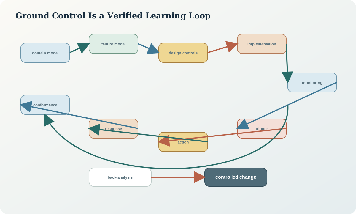
Ground control is a lifecycle system: collect data, establish models, set design criteria, implement the design, verify construction, monitor performance, inspect, respond, review and learn. The controlled document defines roles, competence, communication, exclusion, change, audit and emergency interfaces. It covers both surface and underground excavations where applicable.
The system must connect the design basis to field controls. A report stored separately from excavation instructions does not control risk. Each active sector needs accessible hazard information, current geometry, required support or stand-off, inspection frequency, monitoring status, triggers and escalation path.
Slope failure models
Bench-scale structural models test whether planes or intersections can move toward a free face. Inter-ramp and overall analyses may consider persistent structures, rock-mass strength, weak layers, water and step-path failure. Soil-like or highly weathered materials may require different constitutive and drainage models. Rockfall is a trajectory and catchment problem distinct from global stability.
Choose analysis methods by mechanism. Kinematic analysis tests geometric possibility; limit equilibrium estimates force or moment balance for assumed surfaces; numerical models explore stress, deformation, groundwater coupling and progressive behaviour. None substitutes for a credible ground model and performance observations.
Underground failure and support models
Underground hazards include loose blocks, structurally controlled wedges, stress damage, squeezing, pillar failure, seismic response, fill exposure and interaction between excavations. Opening orientation and sequence can be as important as rock quality. Time-dependent degradation, corrosion, blasting and water alter support demand.
Support design links expected mechanism and demand to component capacity, system interaction, installation quality and allowable deformation. Surface retention, reinforcement and standing or yielding support serve different functions. Record design pattern, installation timing, quality tests, deviations, rehabilitation and exposure limitations.
Data acquisition and observational method
Acquire data at the scale and orientation of the failure model. Sources include oriented core, televiewer, mapping, scan data, laboratory testing, stress measurement, hydraulic observations, blast damage, excavation conformance and support performance. Sampling bias must be explicit: safe accessible faces are not necessarily representative of hazardous ground.
An observational approach defines expected behaviour, credible adverse behaviour, monitoring, thresholds and prepared responses before excavation. It is not informal trial and error. Changes remain within an authorised design envelope or trigger review. The approach depends on timely, reliable observations and genuine ability to act.
Monitoring architecture
Select instruments from the causal model. Survey prisms or radar observe surface movement; extensometers observe relative displacement; piezometers observe head or pressure; load cells and support instrumentation observe selected demand; microseismic systems observe event patterns; inspections observe cracking, ravelling, water and damage. Each has resolution, coverage, latency and failure modes.
Design redundancy across independent evidence types where consequence is high. Monitor the instrument system itself: power, communications, reference stability, calibration, clock, data completeness and environmental effects. A flat line may indicate stability or a failed sensor.
Trigger-action-response plans
A trigger-action-response plan connects measurable state to predetermined action. Levels can reflect normal variability, increased attention, controlled intervention and withdrawal or emergency response, but exact structure and thresholds are site-specific. State the metric, location, filter, persistence, data quality, responsible role, action, communication and reset rule.
Avoid thresholds chosen only from historical noise. They should relate to failure model, design tolerance, instrument capability and response time. Combine absolute level, rate, acceleration, spatial coherence and corroborating observations where appropriate. Never average a local high-consequence signal into a quiet regional value.
Implementation and conformance
Verify that excavation orientation, geometry, blast outcome, support and drainage match the design basis. Record crest and toe, profile, overbreak, underbreak, installed support and unobserved areas. A design is not implemented merely because a drawing was issued.
Conformance deviations are evaluated for mechanism and consequence. Some are benign within tolerance; others change span, daylighting, confinement, load path or water. Define who can accept each class. Preserve the as-built model for monitoring and subsequent analysis.
Review, back-analysis and model learning
Review on planned gates and after material change, trigger exceedance or unexpected performance. Compare prediction ranges with observed behaviour. Back-analysis can constrain parameters or mechanisms, but multiple combinations may fit one displacement history. Retain parameter and model-form uncertainty.
Feed learning into domain boundaries, design criteria, support, monitoring and future data collection. Do not erase the previous model. A good update explains what changed, why, where it applies and how earlier decisions are affected.
Synthetic worked example
A synthetic south wall is divided into competent western and altered eastern sectors. Mapping exposes a wedge-forming joint intersection near their uncertain boundary. In parallel, an underground access beneath the eastern sector shows increasing convergence and intermittent water. Separate teams initially treat the observations independently.
The integrated review identifies a shared weak corridor and hydraulic pathway scenario. It narrows the active surface work zone, adds a piezometer pair and displacement section, checks underground support and drainage, and defines a joint response gate. The evidence does not prove direct hydraulic connection, so both connected and disconnected scenarios remain active.
Practice and ground-control record
Define two surface sectors and two underground domains for a synthetic structure. Assign one failure model, control, observation and response to each. Then produce a ground-control register with domain version, geometry, hazards, design basis, implementation evidence, monitoring, trigger, responsible role, review date or event, deviations and open actions.
The record passes when controls are verifiable, observations are linked to mechanisms, and geology findings are communicated without issuing unauthorised engineering design.
Sources
- Ground control for Western Australian mining operations: code of practice, WorkSafe Western Australia.
- Ground control management guideline, WorkSafe Western Australia.
- Mining and ground falls, National Institute for Occupational Safety and Health.
- Consolidated report on ground or strata failure in underground metalliferous mines, New South Wales Resources Regulator.