B3 · Publication Volume 8
Joints, Fractures and Veins
joint sets, fracture propagation and vein geometry
Learning objectives
After this lesson, you should be able to distinguish a joint from a generic fracture and a mineral vein; recognise opening, sliding and tearing components; use effective normal stress in a simple fracture-reactivation test; interpret cross-cutting and crack-seal textures; and design measurements that separate fracture initiation, propagation, opening, slip, filling and later reactivation.
Start with a field problem
Two steep vein sets cut a layered rock. One set is continuous, mineral filled and locally offsets bedding by centimetres. The other terminates against it, contains repeated fibre bands and has little visible offset. Which set is older? Did either open under high fluid pressure? Are their present apertures original, accumulated through repeated opening, or enlarged by weathering?
The word “fracture” describes a discontinuity, not a complete mechanism. A joint conventionally has little detectable shear displacement. A fault has measurable displacement at the observation scale. A vein is a mineral-filled fracture or tabular mineralised body and may record opening, shear, replacement or combinations. The same surface can change category as scale, exposure and evidence change.
Core process model
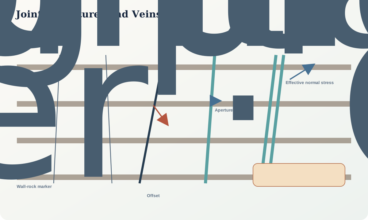
Fracture modes describe local displacement at a crack tip. Mode I opens normal to the fracture plane. Mode II shears within the plane and perpendicular to the crack front. Mode III tears parallel to the crack front. Natural fractures commonly mix modes and interact with layering, anisotropy, nearby cracks and free surfaces.
For frictional reactivation, a simple effective-stress relation is
\tau_f=c+\mu(\sigma_n-P_f),
where \tau_f is shear resistance, c cohesion, \mu friction coefficient, \sigma_n compressive normal stress and P_f connected fluid pressure. Raising P_f lowers effective normal stress and can promote slip. Opening requires fluid pressure and tensile or stress conditions sufficient to overcome the least compressive effective stress and tensile strength, with sign conventions declared.
Crack propagation depends on stress concentration at the tip, flaw geometry, fracture toughness and subcritical chemical processes. Orientation alone does not give magnitude. Fractures may follow bedding, foliation, grain boundaries or earlier veins because those surfaces reduce the energy needed for propagation.
Vein growth can occur by mineral precipitation into open space, repeated crack-seal increments, antitaxial or syntaxial fibre growth, replacement, or combinations. Fibres can track incremental opening direction if their growth relation to the wall is established. Median lines, inclusion bands, wall-rock slivers and sealed microcracks can record repeated events, but later recrystallisation may erase them.
Fracture networks are topological as well as geometric. Connectivity depends on terminations, intersections, relay zones, sealing and scale. High fracture intensity does not guarantee high permeability if fractures are sealed, poorly connected or compressed.
Evidence and measurement
For each fracture, record plane orientation, trace length, termination, aperture, mineral fill, surface morphology, roughness, spacing, offset, abutting and cross-cutting relations, relation to layering, and whether the observation is two- or three-dimensional. Use scanlines or mapped windows with explicit censoring rules: traces leaving the observation window are not equivalent to fully observed lengths.
Distinguish mechanical aperture from present open aperture and vein thickness. Weathering can widen joints; drilling can induce or open fractures; core pieces can rotate; borehole images have resolution and orientation uncertainties. Paired wall markers, slickensides and fibre lineations constrain displacement more directly than a trace.
Under the microscope, document wall-parallel inclusion bands, crystal growth direction, truncation, replacement fronts, deformation twins and reopened seams. Link specimens back to mapped orientations. Geochemistry and fluid inclusions may constrain fluid composition or trapping conditions, but neither identifies the regional source without additional evidence.
Worked example
A fracture carries shear traction \tau=18 MPa and compressive normal stress \sigma_n=85 MPa. Assume c=8 MPa and \mu=0.6. With connected fluid pressure P_f=65 MPa,
\tau_f=8+0.6(85-65)=20\ \text{MPa}.
The predicted resistance exceeds applied shear traction by 2 MPa, so the plane does not reactivate under this simplified static model. If fluid pressure rises to 70 MPa,
\tau_f=8+0.6(85-70)=17\ \text{MPa},
and the plane becomes favourable for slip. A five-megapascal pressure change reverses the result because the initial state was close to failure.
Now consider field evidence: the vein contains four wall-parallel inclusion bands, each enclosing a thin wall-rock sliver, and fibres bridge each increment. The present 8 mm thickness need not represent one 8 mm opening event. A minimum crack-seal interpretation is four increments, but increment widths, dissolution and recrystallisation remain uncertain.
Combine the mechanical sensitivity test with texture. The calculation shows that pressure could promote reactivation; the inclusion bands show repeated opening and sealing; neither alone determines absolute pressure or fluid source.
Misinterpretations and uncertainty
Do not infer principal stress directions from one joint set without testing anisotropy, rotation, mixed-mode propagation and later deformation. Conjugate-looking sets may have different ages. Orthogonal sets can arise sequentially rather than simultaneously.
Present vein thickness is not automatically dilation, fluid volume or displacement. Minerals can replace wall rock, grow into transient porosity or dissolve and reprecipitate. A sealed vein may be a barrier now even if it was a pathway during growth.
Cross-cutting relations provide local relative age. If one fracture terminates against another, the termination may record arrest at an older barrier, later sealing, exposure bias or incomplete mapping. Seek the relation at several intersections and scales.
Practical investigation
Map a rectangular observation window containing at least 30 synthetic or real traces. Record complete, censored and uncertain terminations separately. Calculate orientation sets, spacing along two perpendicular scanlines and a simple connectivity count based on isolated, abutting and crossing nodes. Repeat after changing the minimum visible trace length.
Choose three fractures and write separate hypotheses for initiation, propagation, displacement and filling. Use the effective-stress equation to explore a range of friction, cohesion and fluid pressure. Identify which parameter is measured, which is assumed and which new observation would most reduce uncertainty.
Mastery check
- What distinguishes a joint, fault and vein?
- How does connected fluid pressure affect frictional resistance?
- Why can a thick vein record many small opening increments?
- Why does high fracture intensity not guarantee permeability?
- Which observations make a cross-cutting age relation robust?
Sources and further reading
- Theory of rupture and flow in solids, Griffith, 1921.
- A review of the formation of tectonic veins and their microstructures, Bons, Elburg and Gomez-Rivas, 2012.
- Field relations between dikes and joints, Delaney and others, 1986.