B3 · Publication Volume 8
Fault Geometry and Movement
normal, reverse, strike-slip and oblique faults and slip vectors
Learning objectives
After this lesson, you should be able to record fault strike and dip, measure a lineation or slickenline as trend/plunge or rake, reconstruct a slip vector with an explicit convention, distinguish net slip from throw, heave, separation and apparent offset, classify normal, reverse and strike-slip components, and identify evidence needed to test reactivation and multiple slip events.
Start with a field problem
A fault trace offsets a map contact by 180 m in plan view. Slickensides plunge obliquely, the contact itself dips, and a later dyke crosses the fault without visible offset. Is 180 m the fault displacement? Was movement strike slip, dip slip or oblique? Did the dyke seal an inactive fault, or is the apparent continuity an artefact of exposure?
Map separation is the distance between separated traces of a marker in a chosen view. It depends on the orientation and shape of both marker and fault and need not equal slip. A vertical marker on a vertical strike-slip fault may display net slip clearly, whereas a dipping bed cut by an oblique fault can produce a large or small apparent offset unrelated to the true displacement magnitude. Start from three-dimensional geometry.
Core process model
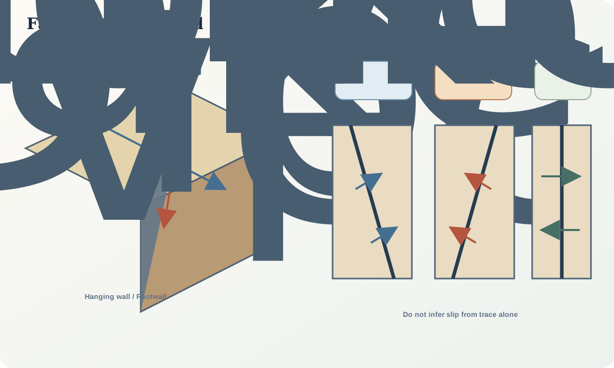
A planar fault is described by strike and dip. A displacement line on the plane may be recorded by trend and plunge in geographic coordinates or by rake measured within the fault plane from a declared strike direction. The slip vector combines magnitude and direction. Its horizontal strike-parallel and down-dip components permit kinematic classification.
The block above an inclined fault is the hanging wall; the block below is the footwall. In normal dip-slip movement the hanging wall moves down relative to the footwall. In reverse movement it moves up; a low-angle reverse fault may be called a thrust under a stated convention. Strike-slip sense is right-lateral or left-lateral when viewed across the fault in map view. Oblique slip contains both components, so forcing it into one end-member discards evidence.
Net slip is the magnitude of relative displacement on the fault. Throw is its vertical component and heave the horizontal component perpendicular to strike for dip-slip geometry. Strike separation and dip separation describe apparent marker displacement measured along specified directions. These quantities coincide only in special configurations.
Faults are zones rather than ideal mathematical planes. A core may contain gouge, breccia, cataclasite, veins or ultracataclasite; a damage zone contains subsidiary fractures and altered rock. At greater temperature or over longer time, displacement may localise in a ductile shear zone. Multiple strands can transfer displacement, link through relays and reactivate different surfaces.
Slip direction may be inferred from displaced markers, slickensides and steps, Riedel shears, drag, asymmetric fibres, focal mechanisms or geodetic displacement. Each has scale and viewing constraints. A polished surface without a reliable step criterion gives a line, not necessarily a sense or unique event.
Evidence and measurement
Measure the fault plane at several sites because orientation can curve. Record whether the measurement represents a discrete surface, zone boundary or average fabric. For slickenlines, retain both rake and the strike direction from which rake was measured, or store trend and plunge directly. Photograph the surface with north, up, scale and viewing direction.
Search for piercing points: originally contiguous features identifiable on both sides in three dimensions. Offset bed contacts are weaker because the original contact extends along a surface. Marker correlation needs lithology, stratigraphy, texture, age or geochemistry, not visual similarity alone.
Map splays, horses, relays, truncations and fault-rock distribution. In core, distinguish natural fractures from drilling-induced breaks and restore core orientation before interpreting movement. In geophysical data, state vertical and horizontal resolution; an apparently sharp reflector termination may represent a zone wider than the image can resolve.
Worked example
A dip-slip fault dips 55° and a restored piercing line indicates 25 m of net slip. The vertical throw is
T=25\sin 55^\circ=20.5\ \text{m},
and the horizontal heave perpendicular to strike is
H=25\cos 55^\circ=14.3\ \text{m}.
Neither value is necessarily the separation seen on a horizontal map because the marker may dip and the ground surface may have relief.
Now suppose a 50 m slip vector has a rake of 30° measured down from the declared strike direction. Its strike-parallel component is 50\cos30^\circ=43.3 m and its down-dip component is 50\sin30^\circ=25.0 m. The fault is oblique slip, dominated by strike-parallel movement. The sign of each component and the chosen strike direction are required to assign lateral and normal/reverse sense.
If a second set of slickensides has a rake near 80° and cuts or polishes the first, do not average the lineations. Treat them as candidate events, map their distribution and seek mineral-growth, fibre, step or offset evidence that orders them.
Misinterpretations and uncertainty
Do not convert map offset directly to displacement. Do not infer lateral sense from a bend in a single trace without reconstructing marker geometry. Drag folds can be inherited, detached from the fault or produced by more than one movement.
Slickenstep criteria can reverse with viewing direction, surface orientation or mineral growth. State whether a step faces toward or away from movement and confirm with another indicator. Fault breccia proves fragmentation but not one slip rate, depth or earthquake.
A straight fault surface in a model is often an interpolation convenience. Natural faults branch, corrugate and terminate. Small orientation errors can move the extrapolated surface substantially at depth. Report an uncertainty envelope rather than only a central plane.
Practical investigation
Build a cardboard or digital block model with one dipping fault and two differently oriented marker planes. Apply a known oblique slip vector. Measure apparent offsets in map and section views, then recover the vector using at least one piercing line. Change marker orientation without changing slip and document how separation changes.
For a mapped fault zone, create a table with observation identifier, plane orientation, lineation, movement sense, criterion, event assignment and confidence. Plot all lineations on the fault plane and test whether one or multiple clusters are present. Keep uncertain measurements visible.
Mastery check
- Why is map separation usually not net slip?
- What information is lost when rake is stored without a strike direction?
- How do throw and heave relate to dip-slip magnitude?
- What makes a feature a piercing point rather than an offset line?
- Which evidence would support two reactivation events on one fault?
Sources and further reading
- Geologic Map Symbol Standard, fault, movement and orientation symbols.
- Fault rocks and fault mechanisms, Sibson, 1977.
- Criteria for the sense of movement on fault surfaces in brittle rocks90145-3), Petit, 1987.