B3 · Publication Volume 8
Structural Controls on Mineralisation
fluid pathways, traps, dilation and reactivation
Learning objectives
After this lesson, you should be able to explain how deformation creates and destroys permeability; identify dilation sites, intersections, competency contrasts and reactive units as testable controls; calculate a simple slip-tendency sensitivity; distinguish pathway, trap, reaction and preservation; integrate vein timing with structural events; and avoid treating favourable structure as proof of mineralisation, continuity or grade.
Start with a field problem
Mineral-filled veins thicken near a fault bend and where the fault crosses a competent bed. Alteration extends farther along the fault than visible mineralisation. Are the bend and bed contact pathways, pressure drops, chemical traps, preservation sites or later structural modifiers? Would the same geometry be favourable elsewhere?
Structure controls opportunities for fluid movement and reaction, but mineral concentration also requires a source, transport mechanism, fluid volume, chemical or physical deposition process, timing and preservation. A geometrically favourable site can be barren. A mineralised site can owe its grade to chemistry rather than unusual dilation. Separate necessary from sufficient conditions.
Core process model
Permeability in deforming rock is dynamic. Fracture opening, slip, grain dilation and reaction can increase connectivity; mineral precipitation, compaction, pressure solution, alteration and stress closure can reduce it. Fault zones can switch between conduit and barrier behaviour across space and time. A sealed vein records former fluid access, not necessarily present flow.
Dilation may localise at releasing bends, stepovers, jogs, fault intersections, fold hinges, vein tips, relay zones and competence boundaries. Whether a site opens depends on fault sense, three-dimensional geometry, stress, fluid pressure and mechanical contrast. The same bend can be releasing under one movement and restraining after reactivation.
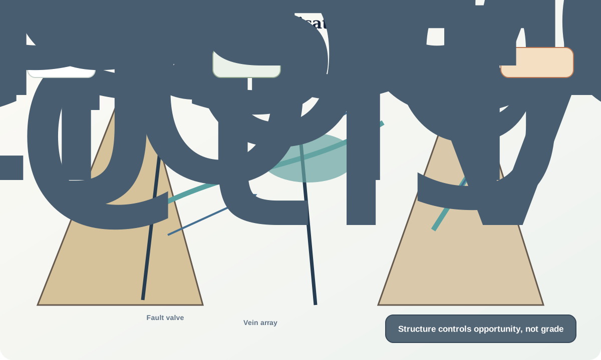
Fluid flow follows hydraulic-potential gradients through connected permeability. Pressure changes during rupture, sealing and reactivation can produce episodic pulses. A fault-valve model describes cycles in which pressure rises behind a low-permeability seal, failure increases permeability, fluid escapes and the system reseals. This is a hypothesis to test with textures, pressure evidence and timing.
Deposition can result from pressure or temperature change, fluid mixing, boiling, wall-rock reaction, phase separation or redox and pH change. Reactive lithologies and alteration fronts can focus chemical exchange even where aperture is small. Structural pathways and geochemical traps may therefore be offset from one another.
Preservation matters. Later faulting can remobilise, disperse or repeat mineralisation; erosion can remove upper levels; metamorphism can recrystallise original textures. A present structural association may combine several events.
Evidence and measurement
Map vein thickness, orientation, density, mineralogy, alteration, brecciation, fault rocks, intersections and distance from structural features. Use unbiased traverses as well as targeted observations. Record barren structures to avoid selection bias. Three-dimensional continuity requires depth data rather than projection from surface alone.
Establish relative timing: does mineral fill seal a fault, get sheared within it, occur on late extension fractures, or replace wall rock adjacent to it? Distinguish pre-, syn- and post-deformation mineral stages with cross-cutting, deformation and growth textures. Link geochronology and geochemistry to those stages.
Measure host-rock properties, permeability anisotropy and reaction fronts where relevant. Geochemical anomalies need background populations, detection limits, sampling support and quality control. An association between structure and anomaly does not establish causation or economic significance.
Worked example
For one fault orientation, resolved shear traction is 22 MPa and compressive normal stress is 70 MPa. With fluid pressure 40 MPa, a cohesionless slip-tendency ratio is
T_s=\frac{\tau}{\sigma_n-P_f}=\frac{22}{70-40}=0.73.
If the friction coefficient is 0.6, this simplified plane is favourable for reactivation. With fluid pressure 30 MPa, T_s=22/40=0.55, below the declared coefficient. The result is sensitive to pressure and says nothing directly about fluid chemistry, permeability duration or mineral grade.
Field mapping shows that mineralised veins occupy a releasing jog only where the fault crosses a reactive carbonate-bearing layer. Barren quartz veins occur in the same jog above and below. A useful working model separates three controls: the jog promoted transient opening, the fault supplied a connected pathway, and the reactive unit promoted deposition. The model predicts alteration along the pathway beyond the mineralised interval and tests the layer rather than projecting grade along the entire fault.
An alternative model is that the carbonate unit already contained permeable stratigraphic horizons and the later fault merely exposed or offset them. Cross-cutting textures, fluid chemistry and three-dimensional contact relations discriminate these histories.
Misinterpretations and uncertainty
Do not rank targets from fault intersections alone. Intersection geometry, movement sense, timing, seal state, depth and host chemistry matter. A density map of structures can reflect exposure and mapping resolution.
Do not assume veins measure fluid flux. Thick veins may grow through many cycles, replacement or local mass transfer. Conversely, large fluid flux can leave subtle alteration rather than thick veins.
Do not extrapolate sampled grade or continuity from a schematic. Structural interpretation guides tests; it does not replace representative sampling, analytical quality control, resource classification or jurisdiction-specific professional requirements.
Practical investigation
Create a synthetic map with two fault sets, folds, three host units and mapped vein stages. Classify every structural site as potential pathway, dilation site, chemical trap, seal or preservation site, allowing multiple roles. Then list the observation supporting each assignment and one contrary observation.
Calculate slip tendency across a range of stress ratios and fluid pressures for all fault orientations. Map sensitivity, not just a preferred result. Compare predictions with both mineralised and barren structures. Build two process models and specify which new oriented core, geochemical or timing data would distinguish them.
Mastery check
- Why can a fault alternate between conduit and barrier?
- What conditions make a bend dilational?
- Why does high slip tendency not predict mineral grade?
- How can a reactive unit shift deposition away from maximum aperture?
- Why must barren structures be included in a structural-control study?
Sources and further reading
- Coupling between deformation, fluid pressures and fluid flow in ore-producing hydrothermal systems, Cox, 2005.
- Fluid flow accompanying faulting, Sibson, 1981.
- A review of the formation of tectonic veins and their microstructures, Bons, Elburg and Gomez-Rivas, 2012.